Abstract
Shear connectors play a vital role in facilitating composite action between the supporting steel beam and concrete slab. This paper explores rebar shear connectors' strength and failure behaviour within solid concrete slabs. The developed finite element model accurately predicted the ultimate shear capacity with the experiment. The average ratio of numerical to experimental predicted load capacity was 1.0 (ranging from 0.76 to 1.2). The FE model was capable of predicting similar failure behaviour observed during experiment. Additionally, the validated FE model was employed to conduct an extensive parametric study. The influence of both rebar strength and concrete grade on the shear performance of rebar connectors with diameters of 16, 20, 25 and 32 mm was evaluated through a detailed parametric analysis. This investigation incorporated concrete strengths of 30, 40 and 50 MPa to assess their impact on connector behaviour. Additionally, the connector strength was varied among 275, 415 and 500 MPa. Higher strength bars exhibit better ductile behaviour compared to lower strength bars. Increasing the concrete compressive strength from 30 to 50 MPa led to an approximate 40% enhancement in the shear capacity of 25 mm diameter rebar connectors with a yield strength of 500 MPa. The effect of increased concrete strength was more pronounced in larger diameter rebars with higher yield strength, which showed greater gains in shear resistance compared to smaller diameter connectors with lower-grade steel. Drawing from the results of 33 parametric push-out simulations, a modified design equation, derived from the AISC 360-16 formulation for headed stud connectors is proposed to estimate the ultimate shear strength of rebar shear connectors embedded within solid concrete slabs.
|
Published in
|
American Journal of Civil Engineering (Volume 14, Issue 2)
|
|
DOI
|
10.11648/j.ajce.20261402.17
|
|
Page(s)
|
112-127 |
|
Creative Commons
|

This is an Open Access article, distributed under the terms of the Creative Commons Attribution 4.0 International License (http://creativecommons.org/licenses/by/4.0/), which permits unrestricted use, distribution and reproduction in any medium or format, provided the original work is properly cited.
|
|
Copyright
|
Copyright © The Author(s), 2026. Published by Science Publishing Group
|
Keywords
Composite, Rebar Connector, Numerical, Finite Element, Load-slip, Push-out
1. Introduction
Composite steel-concrete beam can be defined as a composition of concrete and steel materials so interconnected that the beam responds to loads as a unit. Steel–concrete composite beams are considered a cost-effective structural system for multi-story buildings and bridges. A composite flexure member will have a higher strength and stiffness compared to steel only and reinforced concrete members. This structural system leverages the complementary properties of concrete and steel. In such configurations, concrete contributes compressive capacity, rigidity and structural stability, while steel imparts tensile resistance, ductility and accelerated construction efficiency.
Steel-concrete composite beam comprises of steel I-section and concrete slab attached to the top flange of the steel section. Shear connectors are steel elements affixed to the top flange of steel beams, designed to facilitate effective shear transfer between the steel beam and the composite slab, thereby ensuring composite structural behaviour. They also inhibit any vertical separation or uplift of the slab from the beam. Full composite action is achieved when the connectors can resist the total shear force, provided that either the steel beam has reached its full plastic moment capacity or the effective concrete slab has reached its ultimate compressive stress, whichever occurs first. In cases where full interaction is not achieved, the system exhibits partial composite behaviour.
The most common type of shear connector used in composite floor system is headed studs. For applications subject to very high shear demands, such as heavily loaded bridge girders or floor beams, L-shaped, I-shaped, or C-shaped connectors fabricated from hot-rolled steel sections are sometimes employed. However, these profile-type connectors entail complicate fabrication and higher installation costs compared to headed studs.
In this investigation, a novel shear connector geometry is proposed, consisting of deformed reinforcing bars cut to a prescribed shape. These rebar-based connectors can be fabricated on site by simply cutting standard deformed bars to the required length and configuration. Moreover, their attachment via welding is more straightforward than that of headed studs, leading to savings in both time and labor during installation. The ultimate shear capacity and failure behaviour for various diameter rebar connectors with different types of concrete strength were tested. Since experimental investigations are costly and time-consuming numerical investigations are required to explore the behaviour of rebar shear connectors for a wide range of geometric and material properties of rebar connector and concrete. Moreover, mathematical expressions for calculating shear capacity of the rebar connectors are not available in the current design codes (AISC 360-16
| [1] | AISC 360-16, Specification for structural steel buildings. American Institute of Steel Construction Inc., Chicago, IL., pp. 1-612, 2016. |
[1]
, Eurocode EC4
| [2] | Eurocode 4, Design of composite steel and concrete structures-Part 1.1: General rules and rules for buildings. EN 1994-1-1, European Committee for Standardisation (CEN), Brussels, Belgium., vol. 1, no. 2005, 2005. |
[2]
and BNBC
| [3] | BNBC, Bangladesh National Building Code. Dhaka, Bangladesh., vol. 2, pp. 1999-2001, 2020. |
[3]
). This study complements experimental efforts by implementing nonlinear finite element simulations of push-out test specimens to investigate the ultimate shear capacity and failure mechanisms of deformed rebar connectors, considering a broad spectrum of geometric and material variations.
Considerable research efforts have been carried out to enhance the composite steel-concrete beam performance through the utilization of connectors. Among the various connector types, headed shear connectors have gained significant popularity and widespread use in the modern construction industry. This can be attributed to the through deck welding process and the availability of well-established design guidelines for welded headed shear connectors. The fundamental role of headed stud connectors is to effectively transfer horizontal shear forces across the interface of steel-to-concrete. Moreover, the inclusion of a head in the design serves the crucial purpose of preventing any potential uplift of the concrete slab. The preliminary investigations encompassed comprehensive full-scale push-out tests, encompassing a diverse range of sizes and spacing configurations for the headed studs
. To explore the characteristics and response of welded headed studs within solid slabs, a sophisticated finite element model was formulated
| [5] | Ellobody E. Finite element modeling of shear connection for steel concrete composite girders. Ph.D. thesis, Leeds: School of Civil Engineering, The University of Leeds, 2002. |
| [6] | Lam, D. and El-Lobody, E. Behaviour of headed stud shear connectors in composite beam. Journal of Structural Engineering, ASCE. 2005, 131(1), 96-107.
https://doi.org/10.1061/(ASCE)0733-9445(2005)131:1(96) |
[5, 6]
. An effective numerical model
was utilized to validate test results and compare them with data from established Codes of Practice, including BS5950
| [8] | BS5950, Structural use of steelwork in building. Part4: Code of practice for design of composite slabs with profiled steel sheeting. British Standards Institution, 1994. |
[8]
and AISC
| [9] | AISC 360-05, Specification for structural steel buildings. American Institute of Steel Construction Inc., Chicago, IL, 2005. |
[9]
. To assess large headed stud connectors’ capacity within solid slab, a nonlinear FE model was employed for the push-out analysis
| [10] | Nguyen, H. and Kim, S. Finite element modeling of push-out tests for large stud shear connectors. Journal of Constructional Steel Research. 2009, 65(10-11), 1909- 1920.
https://doi.org/10.1016/j.jcsr.2009.06.010 |
[10]
. Static behaviour of stud shear connectors in high strength structural steel and ultra-high-performance concrete (UHPC) composite were also conducted
| [11] | Du, W., Hu, Z. and Zhou, Z. Analytical Study of Stud Shear Connector Behavior in Steel-UHPC Composite Structures. Buildings. 2024, 14(12), 3807.
https://doi.org/10.3390/buildings14123807 |
| [12] | Hu, Y., Yin, H., Ding, X., Li, S. and Wang, J. Shear behavior of large stud shear connectors embedded in ultra-high-performance concrete, Advances in Structural Engineering. 2020, 23(16), 3401-3414.
https://doi.org/10.1177/1369433220939208 |
| [13] | Tonga, L., Chena, L., Wena, M. and Xub, C. Static behaviour of stud shear connectors in high-strength-steel-UHPC composite beams, Engineering Structures. 2020, 218.
https://doi.org/10.1016/j.engstruct.2020.110827 |
[11-13]
. Another study investigated the performance, failure mechanism, and behaviour of stud shear connectors in steel fiber-reinforced cementitious composites (SFRCC)
| [14] | Fang-wen, W., Yan-peng, F., Jun, D., Guang-qian, W. and Jing-feng, Z. Study on mechanical properties of stud shear connectors in steel-uhpc composite structures, Engineering Mechanics. 2022, 39(2), 222-234, 243.
https://doi.org/10.6052/j.issn.1000-4750.2021.05.0389 |
[14]
. Also, an experimental and numerical study of lightweight aggregate concrete stud connectors was conducted proposing load-slip and shear capacity equations influenced by stirrup spacing, concrete strength, and stud diameter
| [15] | Liu, L., Zhang, L., Zhu, L., Li, J., Yang, Y. and Hao, L. Study on mechanical properties of stud connectors in steel-lightweight aggregate concrete composite structures. Structures. 2023, 47, 1072-1085.
https://doi.org/10.1016/j.istruc.2022.11.145 |
[15]
.
The inclusion of provisions for composite construction in the AISC 360-16
| [1] | AISC 360-16, Specification for structural steel buildings. American Institute of Steel Construction Inc., Chicago, IL., pp. 1-612, 2016. |
[1]
specification has a longstanding history in the United States, dating back to 1936. Notably, in 1961, the AISC specification introduced guidelines for determining the headed connectors shear capacity in solid slabs based on factors such as stud diameter and concrete strength. AISC also considered group and connector position factors to determine nominal shear capacity (
):
(1)
The expressions are;
𝑅𝑔= group effect factor,
𝑅𝑝= position effect factor.
𝐴𝑠𝑐= the cross-sectional area of a connector, mm2
𝐹𝑢= minimum tensile strength of a shear connector respectively, N/mm2
𝑓’c= the compressive cylinder strength, N/mm2
𝐸𝑐= the modulus of elasticity, N/mm2
In the late 1980s, a novel connector known as the Perfobond rib was innovated
| [16] | Leonhardt, E., Andra, H. and Harre, W. New Improved Shear Conector with High Fatigue Strength for Composite Structure. Concrete and Reinforced Concrete Construction. 1987, 12, 325-331. |
[16]
. This connector emerged as a response to the suboptimal performance of headed studs, particularly their susceptibility to fatigue issues arising from live loads on composite bridges. The viability of this shear connector as an alternative to the traditional headed stud connector has been demonstrated through experimental studies
| [17] | Ahn, J., Lee, C., Won, J. and Kim, S. Shear resistance of the Perfobond-rib shear connector depending on concrete strength and rib arrangement. Journal of Constructional Steel Research. 2010, 66(10), 1295-1307.
https://doi.org/10.1016/j.jcsr.2010.04.008 |
| [18] | Jumaat, M., Rahman, M., Alam, M. and Rahman, M. Premature failures in plate bonded strengthened RC beams with an emphasis on premature shear: A review. International Journal of Physical Sciences. 2011, 6(2), 156-168.
https://doi.org/10.5897/IJPS10.369 |
| [19] | Kisa, M. Vibration and stability of multi-cracked beams under compressive axial loading. International Journal of Physical Sciences. 2011, 6(11), 2681-2696.
https://doi.org/10.5897/IJPS11.493 |
[17-19]
, this connector was primarily used in building constructions
. Within the context of a research study examining Perfobond connectors, an alternative connector named the T-Perfobond was introduced by adding a flange to the plate
| [21] | Vianna, J. D. C., Costa-Neves, L. F., da S. Vellasco, P. C. G. and de Andrade, S. A. L. Experimental assessment of Perfobond and T-Perfobond shear connectors' structural response. Journal of Constructional Steel Research. 2009, 65(2), 408-421. https://doi.org/10.1016/j.jcsr.2008.02.011 |
[21]
.
In light of the constraints linked to Perfobond shear connectors and traditional headed studs in composite action, C-shaped connectors emerge as a promising alternative. Headed studs have demonstrated limitations in fatigue performance, notably the development of weld-induced cracks under repeated loading conditions, alongside the necessity for specialized welding tools and high-capacity power sources at construction sites
| [22] | Chromiak, P. and Studnicka, J. Computer model of perfobond connector. Proceedings SDSS. 2006, Lisbon. |
[22]
. Similarly, Perfobond connectors present practical difficulties, particularly when reinforcing bars intersect the perforations, complicating the placement of lower slab reinforcement. To address this issue, an initial study was undertaken
| [23] | Slutter, R. G. and Driscoll, G. C. Flexural Strength of Steel-Concrete Composite Beams. ASCE Journal of Structures Division. 1965, 91 (ST1), 71-99.
https://doi.org/10.1061/JSDEAG.0001257 |
| [24] | Pashan, A. Behaviour of channel shear connectors: push-out tests. M. Sc. Thesis, Department of Civil Engineering, University of Saskatchewan, Canada, 2006. |
[23, 24]
to examine the structural behaviour of channel-type shear connectors and to evaluate their feasibility for use in composite construction. A comparative parametric analysis was performed to predict the shear capacity of these connectors when embedded in high-strength concrete within steel-concrete composite beams
| [25] | Paknahad, M., Shariati, M., Sedghi. Y., Bazzaz, M. and Khorami, M. Shear capacity equation for channel shear connectors in steel-concrete composite beams, Steel and Composite Structures. 2018, 28(4), 483-494. |
[25]
. In another two-phase research program
| [26] | Arıkoğlu, P., Baran, E. and Topkaya, C. Behaviour of channel connectors in steel-concrete composite beams with precast slabs, Journal of Constructional Steel Research. 2020, 172.
https://doi.org/10.1016/j.jcsr.2020.106167 |
[26]
, a steel-concrete composite system for precast slabs was proposed. The research evaluated channel connector strength through shear tests and validated performance with full-scale composite beam experiments. C-shaped connectors are preferred in structures due to their reliable and accepted performance.
Angle shear connectors, lacking a bottom flange, offer a cost-effective and efficient alternative to channel shear connectors in composite beams. By reducing the required amount of steel material, they provide a more economical solution. Research was also conducted on bolted connectors with varying diameters, heights, positions and concrete strength embedded in steel deck
. Another study
| [28] | Yu, J., Wang, Y. H., Li, C. Y., Tan, J. K., Yu, Z., & Shen, Q. W. Experimental study of PZ shear connectors in composite beams. Structures. 2025, 75, 108616.
https://doi.org/10.1016/j.istruc.2025.108616 |
[28]
focused on evaluating the shear capacity of novel puzzle-shaped (PZ) connectors in composite beams, considering hole geometry, connector thickness, and reinforcing bar parameters.
In a recent study
, push-out tests conducted on I-shape connectors revealed a similar behaviour to that observed in channel shear connectors. The Canadian standard code
equation for the channel connectors reliably predicts I-shape shear connectors ultimate load capacity with commendable precision.
While the preceding discussion outlined conventional connectors used in composite steel-concrete beams, there remains a notable deficiency in both the existing literature and current design codes concerning the shear strength and failure mechanisms of rebar-type connectors. To bridge this knowledge gap, current study aims at evaluating rebar connectors’ failure characteristics and structural performance in composite steel-concrete members using standardized push-out tests.
2. Objectives and Scope of the Study
This study aims to experimentally investigate push-out test specimens featuring rebar shear connectors with varying parameters including diameter, height, length and concrete compressive strength. Compare failure modes, load-slip behaviour and shear capacity with developed 3D non-linear finite element simulation in solid concrete slabs under monotonic loading. The FE model is developed using ABAQUS finite element code. The model incorporates the nonlinear material behaviour of concrete and bilinear stress-strain curve of steel and rebar. The interface between concrete and steel is modeled using contact pair algorithm in ABAQUS
| [31] | Hibbitt, Karlsson and Sorensen, Inc. (HKS). Abaqus/CAE User's Guide, Version 2016. |
[31]
. A friction type formulation is defined to simulate the interfacial behaviour between concrete and steel.
A parametric study is conducted using the validated FE model to investigate the effects of strength of rebar connectors and compressive strength of slab concrete. Concrete strength is varied within the range of 30 MPa to 50 MPa. Rebar connectors were assigned yield strengths of 275 MPa, 415 MPa and 500 MPa to capture a representative spectrum of material properties. Deformed reinforcing bars with diameters of 16 mm, 20 mm, 25 mm and 32 mm are used as shear connectors throughout the study. The strength and geometric dimensions of the structural steel section are kept constant during the parametric analysis. The ultimate shear capacity obtained from the parametric study is compared with the results obtained from the AISC
| [1] | AISC 360-16, Specification for structural steel buildings. American Institute of Steel Construction Inc., Chicago, IL., pp. 1-612, 2016. |
[1]
code formula for stud connectors. Finally, modifications have been proposed to the code guidelines to incorporate the deformed rebars as shear connectors in composite members.
3. Experimental Investigation
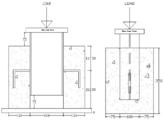
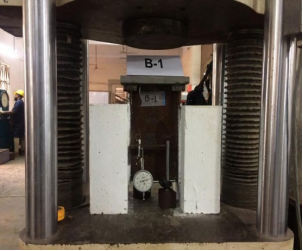
The push-out specimens in this study comprised a hot rolled compact ASTM standard short steel beam (S 8x18.4) section of 350 mm long (
Figure 1) was positioned vertically and supported by two identical reinforced concrete slabs measuring 250 mm by 350 mm with 130 mm thickness. The connection between the steel beam flanges and concrete slabs was achieved using deformed L-shaped rebar shear connectors, which were directly welded to the flanges. Fillet welds of 5/16 in. (8 mm) were applied to 10 mm and 12 mm connectors, while 3/8 in. (10 mm) welds were used for 16 mm and 20 mm connectors using E6013 electrodes. The study explored the influence of concrete compressive strength, between 40 MPa and 50 MPa, and employed 10 mm, 12 mm, 16 mm, and 20 mm diameter rebars.
Figure 1. Push-out experiment using L-sized rebar connector.
To examine the effects of connector size and concrete compressive strength, the specimen geometry remained consistent while varying the connector height between 75 mm and 100 mm. The push-out test specimens featured vertically cast slabs and, in the simulations, a downward axial compression to the top of the steel beam was applied (
Figure 1). The detailed specifications of the specimens are listed in
Table 1.Table 1. Categorization of test specimens.
Sample | Connector height, h (mm) | Concrete Strength, (MPa) | Diameter of Rebar Shear Connector, d (mm) |
B-4b | 75 | 50 | 20 |
B-3b | 16 |
B-2b | 12 |
B-4a | 100 | 50 | 20 |
B-3a | 16 |
B-2a | 12 |
B1 | 10 |
A4 | 100 | 40 | 20 |
A3 | 16 |
A2 | 12 |
A1 | 10 |
The concrete slab was reinforced with two layers, each maintaining a 25 mm clear cover at both the bottom and top surfaces. Each layer included two longitudinal reinforcement bars of #3 (10 mm diameter), supplemented by two additional #3 (10 mm) bars arranged transversely to provide lateral support. Tensile tests were performed using steel coupons extracted from web and flange of steel beam sections using universal testing machine. The coupons were prepared in a dog-bone configuration following BS EN ISO 6892-1
| [32] | BS EN ISO 6892-1, Metallic materials-tensile testing-Part1: Method of test at ambient temperature, 2009. |
[32]
standard, with an 8-inch gauge length and 4-inch grips at both ends. Also, the tensile strengths of deformed rebar connectors were evaluated. Material properties of the yield strength and ultimate strength of steel section and rebar connectors are shown in
Table 2.
Table 2. Material characteristics of rebar connector and steel section.
Sample | Yield Strength, (MPa) | Ultimate Strength, (MPa) |
Steel Section | 307.0 | 424.0 |
Rebar Connector Diameter (mm) | | |
10 | 382.0 | 577.0 |
12 | 403.0 | 628.0 |
16 | 408.0 | 638.0 |
20 | 476.0 | 652.0 |
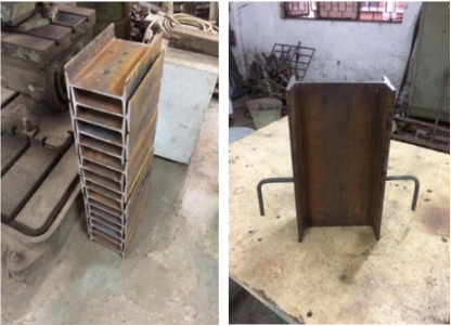
Rebar sections, cut into L-shapes, were prepared from long deformed reinforcing bars in BUET's Strength of Materials Lab. Following welding, these steel specimens were positioned within wooden formwork around the flanges for concrete slab casting, as illustrated (
Figures 2-4). Forms made from plywood were carefully crafted to create a 75 mm gap between the concrete slabs' bottom and the lower steel section, enabling slip during loading.
Figure 2. L-shape rebar connector attached to short steel beam.
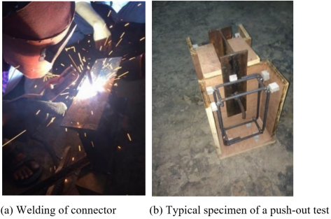
All push-out test slabs were vertically cast following the procedure of Mazoz
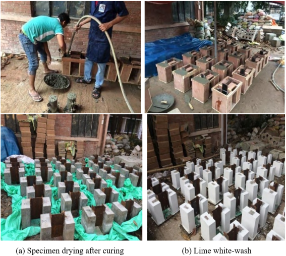
et al. . To minimize concrete strength variations, both slabs originated from the same concrete batch. Concrete mixing adhered to ACI design on 4 by 8-inch cylinders, with slump values checked for workability. Prior to casting, the steel flanges were oiled to eliminate chemical bonding at the steel-concrete interface. Following casting, eleven test specimens were water-cured for 28 days using hessian cloth. After the curing period, the concrete surfaces were whitewashed to ensure clear visibility of crack lines during the loading procedure, facilitating marking of propagating lines.
Figure 3. Push-out test specimen fabrication.
Figure 4. Completion of casting specimens & curing.
Each push-out specimen was evaluated using a Tinius Olsen UTM machine with a maximum capacity of 2000 kN. Two dial gauges of 50 mm were strategically positioned at shear connectors’ level to measure slip with one affixed to the web and other to the flange. Additionally, a separate dial gauge of 5 mm was attached to the side of the concrete slab to record any upward displacement or detachment from the steel throughout the loading process up to failure. Axial load was imposed in a displacement‐controlled manner, advancing 0.5 mm per minute constant rate.
Figure 5. Typical Test Setup & Instrumentation.
The load was applied incrementally during the linear section of the load-slip curve, increasing by 5 kN. In the nonlinear phase, smaller 1~2 kN increments were used to ensure precise assessment of post-peak behaviour after reaching the ultimate load. This loading process, carried out gradually in multiple steps, led to specimen failure within approximately 35 to 45 minutes.
4. Finite Element Modelling
4.1. Geometric Modelling of Reference Test Specimens
In order to expand our understanding of rebar connector behaviour, it is essential to employ computer-aided analysis techniques utilizing finite element methods. Concrete behaviour was characterized using damage plasticity model, which adeptly captures both crushing and cracking phenomena. Under uniaxial compression, stress-plastic strain behaviour followed the Carriera and Chu formulation
| [33] | Carreira, D. J. and Chu, K. M. Stress-Strain Relationship for Plain Concrete in Compression. ACI Journal. 1985, 82 (6), 797-804. |
[33]
. The non-linear behaviour of concrete in tension is defined according to Wang and Hsu
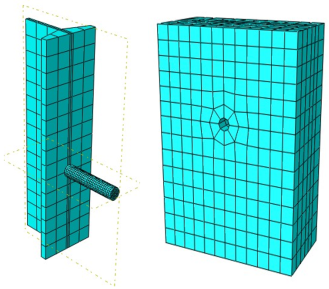
. Since experimental push-out test specimens were symmetric, using symmetry boundary condition half of each of the specimen was modeled (
Figure 6). For simplification purposes within the simulation, the rebar head was excluded. The geometric model was strategically partitioned to enhance result precision and computational efficiency. A mesh size of 3.5 mm was assigned to the connector region, while a coarser 25 mm mesh was applied to the remaining structural elements. All primary components—rebar connectors, concrete slab and steel beam were modeled with C3D8R (8-node solid elements), which is capable of simulating concrete cracking and crushing, posing three degrees of translational freedom at each node. The truss element (T3D2) was used for modeling the reinforcing bars. The push-out specimens’ concrete-steel interaction was represented through the contact pair approach in ABAQUS/Standard
| [31] | Hibbitt, Karlsson and Sorensen, Inc. (HKS). Abaqus/CAE User's Guide, Version 2016. |
[31]
. The coefficient of friction was set to 0.3
based on computational economy and accuracy in predicting the experimental results at the interfaces between concrete and ribbed reinforcing connector surface. Surface of steel flange which is in contact with the concrete slab was also modeled with contact surface. Additionally, tie constraints were used to prevent relative slipping between the steel beam and the shear connectors.
Figure 6. Element meshing of test specimen.
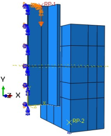
Figure 7. Downward displacement loading.
Loading proceeded under displacement control, applying a downward displacement at the top flange of the steel beam. Implicit general solution strategy was executed. All computational tasks were solved in Abaqus/Standard software using Newton-Raphson direct incremental method. With careful selection of material properties, meshing sizes and interface boundary conditions, the model was validated against test results presented under monotonic loading.
4.2. Performance of FEM
The finite element model was verified against 11 push-out experiments. Observing the results, the performance and limitations of the current models are discussed with respect the ultimate shear capacity, load versus slip behaviour and failure mode of the push-out specimens.
4.2.1. Evaluation of Load-Slip Curves: Experimental Versus Numerical Analysis
Numerically obtained load versus longitudinal slip curves were compared with that obtained from the experiments. These curves were generated by plotting the reaction forces at the support base and the longitudinal displacement of the steel I-section. The longitudinal displacement of the steel I-section is reported as the slip between concrete slab and steel flange which are attached with each other by deformed rebar shear connectors.
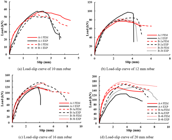
Figure 8 (a)-(d) represents the load-slip responses obtained from both numerical simulations and experimental push-out tests conducted on the 11 specimens analyzed in current study. In general, the simulated load-slip curves were found to match well with the experimentally obtained curves. However, for A4 and B-4b (
Figure 8 (d)) specimens, the significant deviations in the FEM results were observed in comparison with the experimental results. For these specimens the FEM model was found to overestimate the ultimate shear capacity as well as the initial stiffness as obtained in the experimental load versus slip behaviour This mismatch likely stems from inconsistencies in concrete batching–such as variations in mix proportions, aggregate characteristics, casting practices or inadequate curing during specimen preparation. Additionally, residual stresses within the steel sections and minor imperfections in loading alignment or geometry during testing may have further reduced the stiffness and strength captured in the experimental load–slip responses for A4 and B-4b. Furthermore, to explain these phenomena extensive study is required.
Figure 8. Experiment versus numerical load-slip curve.
Also, a variation was observed in the starting portion due to specimen setup in the testing apparatus. In spite of having some differences, the numerical model predicted real-time load-slip situation with eminent accuracy.
4.2.2. Evaluation of Ultimate Load Capacities: Experimental Versus Numerical Analysis
The ultimate shear strengths and corresponding longitudinal slips predicted by the finite element simulations were compared against experimental results, as presented in
Table 3. The ratio of simulated to experimental ultimate capacity (P
FEM/P
EXP) ranged from 0.76 to 1.20, with a standard deviation of 0.12 and average value 1.0. Overall, the numerical model demonstrated high accuracy in estimating the ultimate shear capacity. A2 specimen, however, predicted slightly lower shear capacity than the value observed in the experimental test. On the other hand, for A4 and B-4b specimens the FE model was found to overpredict the experimental capacity by approximately 20%. This might have occurred due to neglecting the effect of residual stress and geometric imperfections during the finite element analysis.
The results indicate that, for 12 mm bars, connector horizontal length has negligible influence on ultimate capacity, as failure is governed by direct shear of the connector. In contrast, for 16 mm and 20 mm connectors, reducing the anchor length from 100 mm to 50 mm slightly enhances capacity by about 12% and 13%, respectively. The load–slip response also shows marginal improvement with shorter anchor lengths for larger diameters, likely due to a shift in failure mode from connector shear to concrete failure.
The FE model effectively reflected how changes in rebar diameter and concrete strength influenced both ultimate load capacity and slip behaviour observed experimentally. The average ratio of numerical to experimental longitudinal slip at ultimate load (SFEM/SEXP) was 0.92 (standard deviation= 0.12). However, the numerical model was not able to predict the slip values with fair accuracy. The performance of the FE model was found to be satisfactory in simulating the experimental load versus slip behaviour of push out specimens constructed with rebar shear connectors.
Table 3. Comparison between numerical and experimental results.
Specimen | Heig-ht (mm) | (MPa) | Dia. (mm) | PFEM (kN) | PEXP (kN) | Pstud (kN) | PFEM/ PEXP | PFEM/ Pstud | Max. Slip at Ultimate load, SFEM (mm) | Max. Slip at Ultimate load, SEXP (mm) | SFEM/ SEXP | Causes of Failure |
B-4b | 75 | 50 | 20 | 178.3 | 153 | 202.5 | 1.17 | 0.88 | 3.57 | 4.73 | 0.75 | Crushing of concrete |
B-3b | 16 | 122.3 | 133.5 | 129.6 | 0.92 | 0.94 | 3.46 | 4.45 | 0.78 | Cracking of concrete |
B-2b | 12 | 81.9 | 79 | 72.9 | 1.04 | 1.12 | 2.94 | 3.03 | 0.97 | Shearing of connector |
B-4a | 100 | 50 | 20 | 168.6 | 165.5 | 202.5 | 1.02 | 0.83 | 3.23 | 3.53 | 0.92 | Crushing of concrete |
B-3a | 16 | 122.1 | 135.5 | 129.6 | 0.9 | 0.94 | 3.24 | 4.04 | 0.80 | Cracking of concrete |
B-2a | 12 | 80.1 | 84.5 | 72.9 | 0.95 | 1.1 | 2.49 | 3.77 | 0.66 | Shearing of connector |
B1 | 10 | 52.8 | 51 | 50.6 | 1.04 | 1.04 | 2.01 | 1.89 | 1.07 | Shearing of connector |
A4 | 100 | 40 | 20 | 151.7 | 126 | 171.3 | 1.2 | 0.89 | 2.66 | 3.66 | 0.73 | Crushing of concrete |
A3 | 16 | 117.6 | 118.1 | 109.6 | 1 | 1.07 | 3.51 | 3.61 | 0.97 | Cracking of concrete |
A2 | 12 | 73.7 | 97.5 | 61.7 | 0.76 | 1.2 | 3.24 | 3.53 | 0.92 | Shearing of connector |
A1 | 10 | 56.5 | 57.5 | 42.8 | 0.98 | 1.32 | 2.39 | 2.46 | 0.97 | Shearing of connector |
| | | | | | Mean | 1 | 1.04 | | | 0.92 | |
| | | | | | S.D. | 0.12 | 0.14 | | | 0.12 | |
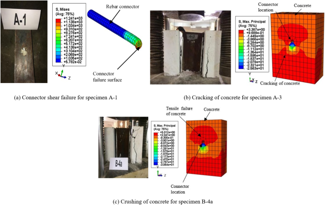
4.2.3. Evaluation of Failure Patterns: Experimental Versus Numerical Analysis
The finite element simulations effectively reproduced the failure patterns demonstrated in the experimental push-out tests. The failure behaviour of the push-out specimens in the numerical study was investigated by observing the stress contours of the constituent materials at the ultimate point of the load versus displacement curve of the specimens. Simulation models utilizing smaller diameter connectors (10 mm and 12 mm), the predominant mode of failure was identified as shear failure of the rebar connectors. On the other hand, specimens featuring larger diameter connectors, the failure mechanism began with concrete crushing, which was subsequently followed by the shearing of the rebar connectors. Similar behaviour was observed in the experiment. For simplicity, the head of the L-shaped connector rebar was neglected during simulation to demonstrate what effect it generates. It was noticed that the head connector has negligible effect on the ultimate shear strength and failure mode. It is due the fact that failure governs mainly concrete crushing or rebar shear. However, more comprehensive study is required to validate this theory.
Figure 9. Typical failure pattern of experimental and numerical specimens.
5. Parametric Study
5.1. Selection of Parameters
Push-out simulations were carried out with varying parameters. They differ from various size and strength of concrete and rebar connectors. For parametric study, parameters were classified in two categories- fixed and variable. The variable parameters comprised concrete strength, rebar connector strength and diameter. These factors were evaluated while maintaining constant geometric properties for the steel beam and concrete slab. Each simulation model comprised of half standard compact short, hot-rolled, beam section (S-shape), specifically an S8x18.4 profile, positioned vertically and embedded within a reinforced concrete slab. The slab dimensions were set at 250 mm by 350 mm with 130 mm thickness. The steel beam used in the study possessed a yield strength of 350 MPa and an ultimate strength of 450 MPa, with a modulus of elasticity measured at 200 GPa.
Concrete compressive strength was differed across three levels-30 MPa, 40 MPa and 50 MPa to assess its influence on structural behaviour. Rebar connectors were analyzed with different yield strength (275 MPa, 415 MPa and 500 MPa) and various diameters such as 16, 20, 25 and 32 mm. The ultimate tensile strength of rebars having yield strength of 275 MPa, 415 MPa and 500 MPa were taken as 360 MPa, 520 MPa and 600 MPa respectively. Rebar connector length was taken as 100 mm throughout this parametric study.
5.2. Results of Parametric Study
The main objective of the current parametric study was to investigate the effects of concrete compressive strength, rebar connector strength and rebar connector diameter on the shear capacity of the rebar connectors in composite beams. Total 33 push-out test specimens were modeled and analysed using the validated finite element model developed in current study. The failure behaviour and the load-slip curve of the parametric specimens were also studied to identify the effects the selected variable parameters. The results of the parametric study are presented in detail in the following sections.
5.2.1. Effects of Concrete Strength
Table 4 illustrates the parametric results of push-out analyses regarding the effects of concrete strength with varying connector strength and diameter.
Table 4. Comparison of parametric results.
Dia. d (mm) | Heig-ht, L (mm) | Rebar strength (MPa) | Concrete Strength, (MPa) | PFEM (kN) | Max. Slip at Ultimate load, SFEM (mm) | P1 (kN) = | P2 (kN) | Pstud (kN) | PFEM/ Pstud | PFEM/ Prebar |
16 | 100 | Fy = 275 | 30 | 72 | 2.08 | 88 | 72 | 72 | 1.00 | 1.16 |
Fu = 360 | 40 | 74 | 2.03 | 110 | 72 | 1.03 | 1.03 |
| 50 | 75 | 1.82 | 130 | 72 | 1.04 | 1.04 |
Fy = 415 | 30 | 99 | 3.14 | 88 | 104 | 88 | 1.13 | 1.60 |
Fu = 520 | 40 | 101 | 2.69 | 110 | 104 | 0.97 | 1.31 |
| 50 | 105 | 2.71 | 130 | 104 | 1.01 | 1.15 |
Fy = 500 | 30 | 109 | 3.51 | 88 | 121 | 88 | 1.24 | 1.76 |
Fu = 600 | 40 | 115 | 3.08 | 110 | 110 | 1.05 | 1.49 |
| 50 | 118 | 2.84 | 130 | 121 | 0.98 | 1.30 |
20 | 100 | Fy = 275 | 30 | 101 | 2.06 | 138 | 113 | 113 | 0.90 | 1.05 |
Fu = 360 | 40 | 101 | 2.02 | 171 | 113 | 0.90 | 0.90 |
| 50 | 103 | 2.27 | 202 | 113 | 0.91 | 0.91 |
Fy = 415 | 30 | 134 | 2.95 | 138 | 163 | 138 | 0.97 | 1.38 |
Fu = 520 | 40 | 141 | 3.63 | 171 | 163 | 0.87 | 1.18 |
| 50 | 144 | 3.36 | 202 | 163 | 0.89 | 1.02 |
Fy = 500 | 30 | 145 | 3.00 | 138 | 188 | 138 | 1.05 | 1.50 |
Fu = 600 | 40 | 156 | 3.03 | 171 | 171 | 0.91 | 1.30 |
| 50 | 161 | 3.73 | 202 | 188 | 0.86 | 1.14 |
25 | 100 | Fy = 275 | 30 | 152 | 2.89 | 216 | 177 | 177 | 0.86 | 1.00 |
Fu = 360 | 40 | 164 | 3.03 | 268 | 177 | 0.92 | 0.92 |
| 50 | 191 | 3.08 | 316 | 177 | 1.08 | 1.08 |
Fy = 415 | 30 | 176 | 2.55 | 216 | 255 | 216 | 0.81 | 1.17 |
Fu = 520 | 40 | 195 | 2.82 | 268 | 255 | 0.76 | 1.04 |
| 50 | 244 | 2.96 | 316 | 255 | 0.96 | 1.10 |
Fy = 500 | 30 | 188 | 2.41 | 216 | 295 | 216 | 0.87 | 1.24 |
Fu = 600 | 40 | 211 | 2.69 | 268 | 268 | 0.79 | 1.13 |
| 50 | 263 | 3.07 | 316 | 295 | 0.89 | 1.19 |
32 | 100 | Fy = 275 | 30 | 196 | 2.15 | 353 | 290 | 290 | 0.68 | 0.79 |
Fu = 360 | 40 | 217 | 2.43 | 438 | 290 | 0.75 | 0.75 |
Fy = 415 | 30 | 220 | 1.91 | 353 | 418 | 353 | 0.62 | 0.89 |
Fu = 520 | 40 | 248 | 2.09 | 438 | 418 | 0.59 | 0.81 |
Fy = 500 | 30 | 232 | 1.79 | 353 | 483 | 353 | 0.66 | 0.94 |
Fu = 600 | 40 | 261 | 1.85 | 438 | 438 | 0.60 | 0.85 |
| | | | | | | | Mean | 0.90 | 1.10 |
| | | | | | | | S.D. | 0.15 | 0.23 |
The table clearly indicates that an increase in concrete strength leads to a higher ultimate load-bearing capacity in the push-out specimens, along with an increase in slip values near the failure point. Specifically, for 20 mm diameter connectors with Fy= 275 MPa, raising the concrete strength from 30 MPa to 50 MPa resulted in only a 2% gain in ultimate shear resistance. However, this enhancement in shear capacity for 20 mm diameter connectors was observed to be 7.5% and 11% respectively for connectors with yield strength 415 MPa and 500 MPa. The increase in ultimate shear capacity with the increase in concrete compressive strength was also found to be less than 10% for 16 mm connectors for the selected steel grades. On the other hand, for 25 mm diameter increase in shear capacity was observed to be 26% (Fy= 275 MPa), 39% (Fy= 415 MPa) and 40% (Fy= 500 MPa) with raise in concrete from 30 MPa to 50 MPa.
Figure 10. Effect of concrete strength with variable connector diameters.
The results indicate that rebar connectors with larger diameters and higher yield strength exhibit a significant increase in shear capacity as concrete strength rises. On the other hand, increasing the concrete strength has negligible impact on the shear capacity of the lower diameter connectors having lower steel grade. This can be explained by observing the failure mechanisms identified through nonlinear finite element analysis of the parametric push-out specimens.
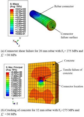
The failure characteristics of push-out specimens in the parametric analysis were investigated by observing the stress contours of the constituent materials at the ultimate point of the load versus displacement curve of the specimens. For steel beam and rebar connectors Von Mises stress contour plots were studied to identify the occurrence of yielding of steel at failure. On the other hand, maximum principal stress contour plots were studied for concrete to identify the occurrence of concrete cracking or crushing at the ultimate load point.
Figure 11. Stress contour at the failure corresponding to the peak point of load versus slip curve.
Specimens using 20 mm connectors reached ultimate capacity when the rebar began to yield (as shown in
Figure 11 (a)). In these specimens, steel yielding occurred first, followed by connector shear failure. Conversely, for the 25 mm and 32 mm connector specimens, the peak load triggered concrete cracking and subsequent crushing of the concrete block (
Figure 11 (b)), with connector yielding appearing only after the ultimate shear capacity had been achieved. Smaller-diameter and lower-grade connectors fail primarily through steel yielding, boosting concrete strength had little influence on their shear capacity.
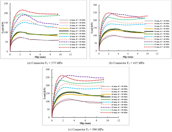
5.2.2. Effects of Connector Strength
Effects of connector yield strength (275 MPa, 415 MPa and 500 MPa) corresponding to varying bar diameters and concrete strengths were analysed. It can be observed from
Table 4 that increasing the connector’s yield strength raises the peak load capacity of the push-out specimens, along with a corresponding change in slip values near the ultimate point. Percentage of increase in ultimate capacity is greater for lower diameter rebars compared to higher diameters with a fixed value of concrete strength. For 16 mm and 20 mm connectors for three selected concrete grades, increasing their steel strength from 275 MPa to 415 MPa elevated ultimate shear capacity by 33 % to 40 % (an average value of 38 %). The average increase in shear capacity was found to be 53% (ranging from 44% to 57%) with the increase in the connector yield strength from 275 MPa to 500 MPa for the three different concrete strength. Therefore, it is obvious that for 16 mm and 20 mm bars effects of connectors yield strength is nearly independent of the concrete strength. In these cases, peak shear is governed by the steel yielding first and then connector shearing.
The average increase in ultimate shear capacity for 25 mm bar was found to be around 20% and 30% respectively for the increase in steel grade from 275 MPa to 415 MPa and 500 MPa respectively, covering the concrete strength from 30 MPa to 50 MPa. Similarly, 13% and 19% capacity enhancement was observed for the same change in material strength for 32 mm rebars. For higher diameter bars crushing of concrete governs the failure behaviour, which is the reason behind the decrease in capacity enhancement with the increase in steel grade as compared lower diameter rebars.
Table 4 also shows the slip values corresponding to the ultimate point in the load versus slip curve attained from the FE analysis of the parametric push-out specimens. The lower diameter bars show increase in the slip values with increase in the steel grade. Almost similar changes are observed for the three types of concrete selected. This increase in slip of the connectors with increasing steel grade results from the increased yield strain of higher-grade steel. However, for higher diameter bars the slip at the ultimate point is observed to be decreased with the increase in connector steel grade. For specimens with 25 mm and 32 mm connectors, failure initiated with concrete cracking at peak load, then progressed to crushing of the concrete block and eventual yielding of connectors. However, the computed slip values for the parametric push-out tests using 50 MPa concrete showed notable inconsistencies. The nonlinear material behaviour for high strength concrete may not be simulated appropriately in the current FEM model.
5.2.3. Effects of Diameters
Ultimate load capacity of the rebar shear connectors increases with diameters. This behaviour is observed for 30 MPa, 40 MPa and 50 MPa concrete with the various steel grades for connectors. However, the slip values resembling to the ultimate load points were found to be decreased with the increase in diameters. For connectors with lower diameters, bending of the connectors occur with the increase in the applied loading and finally failure occurs through the shearing of the connectors at the interface. Due to excessive bending deformation the ductile failure mode is observed for connectors with lower diameters. However, for lower h/d ratio (which was attained in this study by increasing the diameter for a fixed value of h i.e., 100 mm) higher ultimate capacity accompanied by lower characteristic slip value is observed (
Table 4). The higher capacity is obtained due to the higher bearing area of concrete due to the increase in connector diameter. For 50 MPa concrete, lower slip values at the ultimate point was observed for 16 mm rebar as compared to 25 mm rebar. Further experimental study on high strength concrete is necessary with variations in connector height (h) and diameter (d) to validate these finding from the numerical simulations.
6. Code Comparison of Parametric Results
The lack of design rules for the rebars shear connectors is a major challenge for the wider use of these type of connectors in composite construction. In this regard an attempt has been made to investigate the suitability of AISC 360-16
| [1] | AISC 360-16, Specification for structural steel buildings. American Institute of Steel Construction Inc., Chicago, IL., pp. 1-612, 2016. |
[1]
capacity prediction equation of stud connectors for determining rebar connectors shear capacity in composite members. Considering the group and position effect factor of value 1, the current American Standard (AISC, 2016) predicts nominal shear capacity (P
stud) of a headed stud embedding solid concrete slab using Eq. (
2).
(2)
The experimental investigation involved rebar connectors of different diameters (10 mm, 12 mm, 16 mm, and 20 mm) and varying concrete strengths of 40 MPa and 50 MPa, respectively. Since no standard formula exists for rebar shear connectors, we propose a revised design expression (Eq. (
3)), which applies a 0.7 correction factor to the AISC 360-16 stud connector equation based on the observed ultimate capacities of rebar shear connectors.
(3)
The parametric results of the push-out specimens analysed in current study were compared with the AISC equations for stud connectors as well as with the proposed equation (Eq. (
3)). The results are presented in
Table 4.
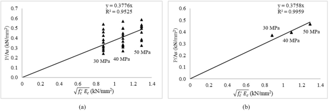
Figure 12. Parametric diagram of vs for (a) all specimens (b) average value corresponding to concrete strength.
The acceptability of Eq. (
3) was checked with respect to all 33 parametric simulation results.
vs
diagram of all the simulations show that the modification factor 0.7 to AISC 360-16
| [1] | AISC 360-16, Specification for structural steel buildings. American Institute of Steel Construction Inc., Chicago, IL., pp. 1-612, 2016. |
[1]
stud connector equation can be used to evaluate the shear capacity of rebar connectors.
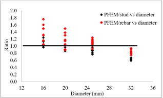
Figure 13. Ultimate shear capacity ratio of numerical to design equations.
It is observed that the mean value of P
FEM/P
stud was found to be 0.90 with 0.15 standard deviation and mean value of P
FEM/P
rebar was found to be 1.10 with standard deviation of 0.23. The average value of P
FEM/P
rebar for 16 mm, 20 mm, 25 mm and 32 mm are 1.32, 1.15, 1.10 and 0.84 respectively and the average value of P
FEM/P
stud are 1.05, 0.92, 0.88 and 0.65 respectively. The proposed capacity equation (Eq. (
3)) provided conservative results for 16 mm, 20 mm and 25 mm connectors as compared to AISC 360-16 equation except for 32 mm diameter connectors. The AISC formula for stud connectors tends to overestimate the capacity of 25 mm and 32 mm rebar connectors, as it was originally derived from tests on studs with an h/d ≥ 4.0.
For higher diameter stud connectors having h/d < 4, concrete fails before the stud shear-off.
Concrete failure leads to a significant decrease in connector strength, a factor not accounted for in the AISC code’s stud connector equation. In current study the height of the connectors was kept at a fixed value of 100 mm resulting in a h/d ratio of 3 for 32 mm diameter connectors. Therefore, the AISC 360-16 guidelines for stud connectors require modifications before applying the rules for rebar connectors. However, the modified Eq. (
3) based on test data for rebar connectors can be applied for predicting the capacity of rebar connectors with diameter less than 25 mm (h/d ratio greater than 4). This equation (Eq. (
3)) results in unsafe prediction for 32 mm diameter connectors. Experimental test results are needed to develop adjustments to the formula for estimating rebar connectors shear capacity exceeding 25 mm diameter.
7. Conclusions and Recommendations
This research combined experimental testing with 3D nonlinear FE modeling to replicate the push-out peformance of rebar connector in concrete slab. The shear capacity and load versus behaviour of rebar connectors were studied with variable rebar strength, diameters and concrete strength. Effects of these parameters were studied on a fixed geometric property for steel beam and slab. The shear capacity obtained from the finite element simulations were also compared with AISC 360-16
| [1] | AISC 360-16, Specification for structural steel buildings. American Institute of Steel Construction Inc., Chicago, IL., pp. 1-612, 2016. |
[1]
formula for stud connectors.
In this study, within its specific scope, the following conclusions were drawn:
1) The developed FE model demonstrated excellent accuracy in anticipating the ultimate shear capacity of rebar connector in the present study. The ratio of numerical to experimental ultimate capacity ranged between 0.76 to 1.20, with 1.0 as average value (std dev.= 0.12). The model was capable of simulating experimental failure mode and showed similar load versus displacement results as observed in the push-out tests.
2) In the parametric study, 33 specimens divided into four groups (16 mm, 20 mm, 25 mm and 32 mm diameter) of different concrete strengths of 30 MPa, 40 MPa and 50 MPa and various steel rebar strength were analysed. For 16 mm and 20 mm connectors maximum 5.5% increase was observed in the ultimate shear capacity for the increase in concrete strength from 30 MPa to 40 MPa. This increase in shear capacity was found to be maximum 12.7% for 25 mm and 32 mm connectors. With enhancement in concrete from 30 MPa to 50 MPa, a significant 40% rise in shear capacity was achieved for 25 mm connectors having Fy= 500 MPa. The findings indicate that, in the case of larger diameter rebars with higher yield strength, an increase in concrete strength leads to a notable enhancement in shear capacity. Conversely, the shear capacity of smaller diameter connectors with lower steel grade is minimally affected by an increase in concrete .
3) Average increase in ultimate shear capacity regarding 25 mm bar was found to be around 20% and 30% respectively for the increase in steel grade from 275 MPa to 415 MPa and 500 MPa respectively. This is applicable for concrete strength of 30 MPa, 40 MPa and 50 MPa as selected in the current study. The average increase in capacity was found to be 13% and 19% for similar change in material strength for 32 mm rebars. For higher diameter bars crushing of concrete governs the failure behaviour, which is the reason behind the decrease in capacity enhancement with the increase in steel grade.
4) High-strength rebars exhibit greater ductile behaviour whereas lower strength bars display less ductile behaviour. For 16 mm rebars 69% (= 30 MPa) and 56% (= 50 MPa) increase in slip were observed changing the yield capacity from 275 MPa to 500 MPa. Similar rise in slip was noticed for 20 mm as well. But for 25 mm and 32 mm rebars slip values decreased for changing the yield strength for a specific concrete compressive strength.
5) Higher diameter bars showed improved shear resistance as compared to the lower diameter bars due to larger area. It was also observed that lower diameter bars fail by shearing of connectors while larger ones by cracking of concrete around the shear connector.
6) The shear capacity of rebar shear connectors is overestimated by the AISC 360-16 design formula. The modified equation (Eq. (
3)), derived from push-out testing, can be applied for predicting rebar connectors capacity with diameter less than 25 mm and h/d ≥4. However, this equation results in unsafe prediction for 32 mm diameter connectors.
Abbreviations
AISC | American Institute of Steel Construction |
BNBC | Bangladesh National Building Code |
BS | British Standards |
CSA | Canadian Standards Association |
EC4 | Eurocode 4 |
EN | European Norm or European Standard |
ISO | International Organization for Standardization |
P | Nominal Shear Capacity |
𝑓’c | Concrete Compressive Strength |
𝑓y | Steel Yield Strength |
Smax | Slip at Ultimate Load Point |
Author Contributions
Delphian Dip Sen: Conceptualization, Investigation, Validation, Software, Formal Analysis, Visualization, Data curation, Resources, Methodology, Writing – original draft, Writing – review & editing
Mohammad Hosainul Kabir: Formal Analysis, Resources
Mahbuba Begum: Conceptualization, Funding acquisition, Supervision, Project administration
Conflicts of Interest
The authors declare no conflicts of interest.
References
| [1] |
AISC 360-16, Specification for structural steel buildings. American Institute of Steel Construction Inc., Chicago, IL., pp. 1-612, 2016.
|
| [2] |
Eurocode 4, Design of composite steel and concrete structures-Part 1.1: General rules and rules for buildings. EN 1994-1-1, European Committee for Standardisation (CEN), Brussels, Belgium., vol. 1, no. 2005, 2005.
|
| [3] |
BNBC, Bangladesh National Building Code. Dhaka, Bangladesh., vol. 2, pp. 1999-2001, 2020.
|
| [4] |
Viest, I. M. Review of research on composite steel-concrete beams. Journal of the Structural Division, ASCE. 1960, 86 (ST6), Paper 2496, 1-21.
https://doi.org/10.1061/JSDEAG.0000525
|
| [5] |
Ellobody E. Finite element modeling of shear connection for steel concrete composite girders. Ph.D. thesis, Leeds: School of Civil Engineering, The University of Leeds, 2002.
|
| [6] |
Lam, D. and El-Lobody, E. Behaviour of headed stud shear connectors in composite beam. Journal of Structural Engineering, ASCE. 2005, 131(1), 96-107.
https://doi.org/10.1061/(ASCE)0733-9445(2005)131:1(96)
|
| [7] |
Lam, D. and EI-Lobody, E. Finite element modelling of headed stud shear connectors in steel-concrete composite beam. In: Structural Engineering, Mechanics and Computation. 2001, 401-408.
https://doi.org/10.1016/B978-008043948-8/50041-2
|
| [8] |
BS5950, Structural use of steelwork in building. Part4: Code of practice for design of composite slabs with profiled steel sheeting. British Standards Institution, 1994.
|
| [9] |
AISC 360-05, Specification for structural steel buildings. American Institute of Steel Construction Inc., Chicago, IL, 2005.
|
| [10] |
Nguyen, H. and Kim, S. Finite element modeling of push-out tests for large stud shear connectors. Journal of Constructional Steel Research. 2009, 65(10-11), 1909- 1920.
https://doi.org/10.1016/j.jcsr.2009.06.010
|
| [11] |
Du, W., Hu, Z. and Zhou, Z. Analytical Study of Stud Shear Connector Behavior in Steel-UHPC Composite Structures. Buildings. 2024, 14(12), 3807.
https://doi.org/10.3390/buildings14123807
|
| [12] |
Hu, Y., Yin, H., Ding, X., Li, S. and Wang, J. Shear behavior of large stud shear connectors embedded in ultra-high-performance concrete, Advances in Structural Engineering. 2020, 23(16), 3401-3414.
https://doi.org/10.1177/1369433220939208
|
| [13] |
Tonga, L., Chena, L., Wena, M. and Xub, C. Static behaviour of stud shear connectors in high-strength-steel-UHPC composite beams, Engineering Structures. 2020, 218.
https://doi.org/10.1016/j.engstruct.2020.110827
|
| [14] |
Fang-wen, W., Yan-peng, F., Jun, D., Guang-qian, W. and Jing-feng, Z. Study on mechanical properties of stud shear connectors in steel-uhpc composite structures, Engineering Mechanics. 2022, 39(2), 222-234, 243.
https://doi.org/10.6052/j.issn.1000-4750.2021.05.0389
|
| [15] |
Liu, L., Zhang, L., Zhu, L., Li, J., Yang, Y. and Hao, L. Study on mechanical properties of stud connectors in steel-lightweight aggregate concrete composite structures. Structures. 2023, 47, 1072-1085.
https://doi.org/10.1016/j.istruc.2022.11.145
|
| [16] |
Leonhardt, E., Andra, H. and Harre, W. New Improved Shear Conector with High Fatigue Strength for Composite Structure. Concrete and Reinforced Concrete Construction. 1987, 12, 325-331.
|
| [17] |
Ahn, J., Lee, C., Won, J. and Kim, S. Shear resistance of the Perfobond-rib shear connector depending on concrete strength and rib arrangement. Journal of Constructional Steel Research. 2010, 66(10), 1295-1307.
https://doi.org/10.1016/j.jcsr.2010.04.008
|
| [18] |
Jumaat, M., Rahman, M., Alam, M. and Rahman, M. Premature failures in plate bonded strengthened RC beams with an emphasis on premature shear: A review. International Journal of Physical Sciences. 2011, 6(2), 156-168.
https://doi.org/10.5897/IJPS10.369
|
| [19] |
Kisa, M. Vibration and stability of multi-cracked beams under compressive axial loading. International Journal of Physical Sciences. 2011, 6(11), 2681-2696.
https://doi.org/10.5897/IJPS11.493
|
| [20] |
Ferreira, L., de Andrade, S. and Vellasco, P. A design model for bolted composite semi-rigid connections. Stability and ductility of steel structures. 1998, 293.
https://doi.org/10.1016/B978-008043320-2/50026-5
|
| [21] |
Vianna, J. D. C., Costa-Neves, L. F., da S. Vellasco, P. C. G. and de Andrade, S. A. L. Experimental assessment of Perfobond and T-Perfobond shear connectors' structural response. Journal of Constructional Steel Research. 2009, 65(2), 408-421.
https://doi.org/10.1016/j.jcsr.2008.02.011
|
| [22] |
Chromiak, P. and Studnicka, J. Computer model of perfobond connector. Proceedings SDSS. 2006, Lisbon.
|
| [23] |
Slutter, R. G. and Driscoll, G. C. Flexural Strength of Steel-Concrete Composite Beams. ASCE Journal of Structures Division. 1965, 91 (ST1), 71-99.
https://doi.org/10.1061/JSDEAG.0001257
|
| [24] |
Pashan, A. Behaviour of channel shear connectors: push-out tests. M. Sc. Thesis, Department of Civil Engineering, University of Saskatchewan, Canada, 2006.
|
| [25] |
Paknahad, M., Shariati, M., Sedghi. Y., Bazzaz, M. and Khorami, M. Shear capacity equation for channel shear connectors in steel-concrete composite beams, Steel and Composite Structures. 2018, 28(4), 483-494.
|
| [26] |
Arıkoğlu, P., Baran, E. and Topkaya, C. Behaviour of channel connectors in steel-concrete composite beams with precast slabs, Journal of Constructional Steel Research. 2020, 172.
https://doi.org/10.1016/j.jcsr.2020.106167
|
| [27] |
Langarudi, P. A. and Ebrahimnejad, M. Numerical study of the behavior of bolted shear connectors in composite slabs with steel deck, Structures. 2020, 26, pp. 501-515.
https://doi.org/10.1016/j.istruc.2020.04.037
|
| [28] |
Yu, J., Wang, Y. H., Li, C. Y., Tan, J. K., Yu, Z., & Shen, Q. W. Experimental study of PZ shear connectors in composite beams. Structures. 2025, 75, 108616.
https://doi.org/10.1016/j.istruc.2025.108616
|
| [29] |
Mazoz, A., Benanane, A. and Titoum, M. Push-out Tests on a new Connector of I-shape, International Journal of Steel Structures. 2013, 13(3), 519-528.
https://doi.org/10.1007/s13296-013-3011-4
|
| [30] |
CAN/CSA-S16-01 Limit states design of steel structures. Canadian Standard Association, Toronto, Ontario, Canada, 2001.
https://doi.org/10.12989/scs.2018.28.4.483
|
| [31] |
Hibbitt, Karlsson and Sorensen, Inc. (HKS). Abaqus/CAE User's Guide, Version 2016.
|
| [32] |
BS EN ISO 6892-1, Metallic materials-tensile testing-Part1: Method of test at ambient temperature, 2009.
|
| [33] |
Carreira, D. J. and Chu, K. M. Stress-Strain Relationship for Plain Concrete in Compression. ACI Journal. 1985, 82 (6), 797-804.
|
| [34] |
Wang, T., & Hsu, T. T. Nonlinear finite element analysis of concrete structures using new constitutive models. Computers & Structures. 2001, 79(32), 2781-2791.
https://doi.org/10.1016/S0045-7949(01)00157-2
|
| [35] |
Begum, M., Driver, R. G. and Elwi, A. E. Finite element modeling of partially encased composite columns using the dynamic explicit solution method. Journal of Structural Engineering. 2007, 133(3), 326-334.
https://doi.org/10.1061/(ASCE)0733-9445(2007)133:3(326)
|
Cite This Article
-
APA Style
Sen, D. D., Kabir, M. H., Begum, M. (2026). Strength and Failure Behaviour of Welded Rebar Shear Connectors in Composite Beam with Solid Concrete Slab. American Journal of Civil Engineering, 14(2), 112-127. https://doi.org/10.11648/j.ajce.20261402.17
 Copy
|
Copy
|
 Download
ACS Style
Sen, D. D.; Kabir, M. H.; Begum, M. Strength and Failure Behaviour of Welded Rebar Shear Connectors in Composite Beam with Solid Concrete Slab. Am. J. Civ. Eng. 2026, 14(2), 112-127. doi: 10.11648/j.ajce.20261402.17
Copy
|
Download
AMA Style
Sen DD, Kabir MH, Begum M. Strength and Failure Behaviour of Welded Rebar Shear Connectors in Composite Beam with Solid Concrete Slab. Am J Civ Eng. 2026;14(2):112-127. doi: 10.11648/j.ajce.20261402.17
Copy
|
Download
-
@article{10.11648/j.ajce.20261402.17,
  author = {Delphian Dip Sen and Mohammad Hosainul Kabir and Mahbuba Begum},
  title = {Strength and Failure Behaviour of Welded Rebar Shear Connectors in Composite Beam with Solid Concrete Slab},
  journal = {American Journal of Civil Engineering},
  volume = {14},
  number = {2},
  pages = {112-127},
  doi = {10.11648/j.ajce.20261402.17},
  url = {https://doi.org/10.11648/j.ajce.20261402.17},
  eprint = {https://article.sciencepublishinggroup.com/pdf/10.11648.j.ajce.20261402.17},
  abstract = {Shear connectors play a vital role in facilitating composite action between the supporting steel beam and concrete slab. This paper explores rebar shear connectors' strength and failure behaviour within solid concrete slabs. The developed finite element model accurately predicted the ultimate shear capacity with the experiment. The average ratio of numerical to experimental predicted load capacity was 1.0 (ranging from 0.76 to 1.2). The FE model was capable of predicting similar failure behaviour observed during experiment. Additionally, the validated FE model was employed to conduct an extensive parametric study. The influence of both rebar strength and concrete grade on the shear performance of rebar connectors with diameters of 16, 20, 25 and 32 mm was evaluated through a detailed parametric analysis. This investigation incorporated concrete strengths of 30, 40 and 50 MPa to assess their impact on connector behaviour. Additionally, the connector strength was varied among 275, 415 and 500 MPa. Higher strength bars exhibit better ductile behaviour compared to lower strength bars. Increasing the concrete compressive strength from 30 to 50 MPa led to an approximate 40% enhancement in the shear capacity of 25 mm diameter rebar connectors with a yield strength of 500 MPa. The effect of increased concrete strength was more pronounced in larger diameter rebars with higher yield strength, which showed greater gains in shear resistance compared to smaller diameter connectors with lower-grade steel. Drawing from the results of 33 parametric push-out simulations, a modified design equation, derived from the AISC 360-16 formulation for headed stud connectors is proposed to estimate the ultimate shear strength of rebar shear connectors embedded within solid concrete slabs.},
 year = {2026}
}
Copy
|
Download
-
TY  - JOUR
T1  - Strength and Failure Behaviour of Welded Rebar Shear Connectors in Composite Beam with Solid Concrete Slab
AU  - Delphian Dip Sen
AU  - Mohammad Hosainul Kabir
AU  - Mahbuba Begum
Y1  - 2026/04/21
PY  - 2026
N1  - https://doi.org/10.11648/j.ajce.20261402.17
DO  - 10.11648/j.ajce.20261402.17
T2  - American Journal of Civil Engineering
JF  - American Journal of Civil Engineering
JO  - American Journal of Civil Engineering
SP  - 112
EP  - 127
PB  - Science Publishing Group
SN  - 2330-8737
UR  - https://doi.org/10.11648/j.ajce.20261402.17
AB  - Shear connectors play a vital role in facilitating composite action between the supporting steel beam and concrete slab. This paper explores rebar shear connectors' strength and failure behaviour within solid concrete slabs. The developed finite element model accurately predicted the ultimate shear capacity with the experiment. The average ratio of numerical to experimental predicted load capacity was 1.0 (ranging from 0.76 to 1.2). The FE model was capable of predicting similar failure behaviour observed during experiment. Additionally, the validated FE model was employed to conduct an extensive parametric study. The influence of both rebar strength and concrete grade on the shear performance of rebar connectors with diameters of 16, 20, 25 and 32 mm was evaluated through a detailed parametric analysis. This investigation incorporated concrete strengths of 30, 40 and 50 MPa to assess their impact on connector behaviour. Additionally, the connector strength was varied among 275, 415 and 500 MPa. Higher strength bars exhibit better ductile behaviour compared to lower strength bars. Increasing the concrete compressive strength from 30 to 50 MPa led to an approximate 40% enhancement in the shear capacity of 25 mm diameter rebar connectors with a yield strength of 500 MPa. The effect of increased concrete strength was more pronounced in larger diameter rebars with higher yield strength, which showed greater gains in shear resistance compared to smaller diameter connectors with lower-grade steel. Drawing from the results of 33 parametric push-out simulations, a modified design equation, derived from the AISC 360-16 formulation for headed stud connectors is proposed to estimate the ultimate shear strength of rebar shear connectors embedded within solid concrete slabs.
VL  - 14
IS  - 2
ER  -
Copy
|
Download