This article presents the structural concept of the shaft support system for vertical shaft machines, describing its design features, manufacturing process, and the functional role of the rubber element positioned between the bushings. The study also examines the improved lubrication system and explains the purpose of shaping the lower inner part of the housing in a hemispherical form, emphasizing the damping function provided by the rubber damper installed in this area. In addition, the paper investigates the twist angle of the helical grooves formed along the shaft in the direction opposite to shaft rotation, the operating rotational speed, and the influence of elastic components within the support assembly on deflection behavior. Experimental test results obtained using weight-based wear measurement techniques are presented to evaluate the durability and performance characteristics of the improved support structure.
| Published in | American Journal of Mechanics and Applications (Volume 12, Issue 4) |
| DOI | 10.11648/j.ajma.20251204.15 |
| Page(s) | 102-108 |
| Creative Commons |
This is an Open Access article, distributed under the terms of the Creative Commons Attribution 4.0 International License (http://creativecommons.org/licenses/by/4.0/), which permits unrestricted use, distribution and reproduction in any medium or format, provided the original work is properly cited. |
| Copyright |
Copyright © The Author(s), 2025. Published by Science Publishing Group |
Housing, Bushing, Bearing, Rubber Damper, Shaft, Base Plate, Helical Grooves, Lubricating Material
 (1)
(1)  -Weight of the component before testing (g).
  - Weight of the component after testing (g).
  - Mass loss (g).
  (2)
(2)  (3)
(3)  ,
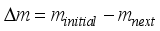
,  and until
  It can be observed that when increased, the wear rate of the inner part of the composite bushing ranged from 1.48% to 1.31%, achieving a reduction of up to 0.17% (Figure 9).
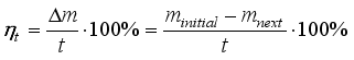
  fixed, and the shaft rotates at 35–45 rpm, an increase in the stiffness coefficient of the elastic element in the shaft support resulted in the wear rate of the bronze part in the support rising from 1.33% to 1.47% (Figure 10).
| Weight of the Component Before Testing(g) |
| Weight of the Component After Testing (g) |
| Mass Loss (g) |
| [1] | Sh. A. Shoobidov. Machine Parts. Textbook. Tashkent: “O‘zbekiston Milliy Ensiklopediyasi” State Scientific Publishing, 2014; p. 374. |
| [2] | A. Jo‘rayev, R. Tojiboyev. Applied Mechanics. Tashkent: “Fan va Texnologiya”, 2007; 288 p. |
| [3] | V. A. Dmitriev. Machine Parts: Fundamentals of Calculation and Design of Machines. Leningrad: “Sudostroenie”, 1970, pp. 641–649. |
| [4] | A. J. Jo‘rayev et al. Theory of Machines and Mechanisms. Tashkent: Gafur G‘ulom, 2004; p. 408. |
| [5] | John J. Uicker, Jr. Theory of Machines and Mechanisms. New York: Oxford University Press, 2017; 978 pp. |
| [6] | P. I. Orlov. Fundamentals of Design, Vol. 2. Moscow: Mashinostroenie, 1988, pp. 372–373, 385–387, 399-404. |
| [7] | Thrust Sliding Bearing Assembly. UZ FAP 2752. Published: 26.06.2025. Bulletin No. 6(291). |
| [8] | Sh. Kenjaboev, N. Muydinova, A. Akbarov, F. Nishonov. Thrust Sliding Bearing Assembly. Scientific Journal Mechanics and Technology, No. 3(20), 2025. |
| [9] | Sh. Kenjaboev, N. Muydinova, A. Akbarov, F. Nishonov. Thrust Sliding Bearing Assembly. Scientific Journal Science, Research, and Development, 2025, No. 4(12). |
| [10] | T. B. Minigaliev, V. P. Dorozhkin. Technology of Rubber Products: Textbook. Kazan: Kazan State Technological University Publishing, 2009; 236 p. |
| [11] | O. Ikromov. Tribology. Friction and Wear. Tashkent: Uzbekistan, 2003; 336 p. |
| [12] | D. N. Garkunov. Tribology: Design, Manufacturing, and Operation of Machines. Moscow: MSHA Publishing, 2002; 626 p. |
| [13] | A. Djuraev, Sh. Kenjaboev, A. Akbarov. Development of Design and Calculation of Frictional Force in Rotational Kinematic Pair of the Fifth Class with Longitudinal Grooves. International Journal of Advanced Research in Science, Engineering and Technology, India, 2018, No. 9, pp. 6759-6763. |
| [14] | I. V. Kragelsky. Friction and Wear. Moscow: Mashinostroenie, 1968; 482 p. |
| [15] | A. V. Lavrin, V. B. Bolyakin, V. B. Ossialalar. Experimental Study of Friction Torque in a Rolling Bearing under Shaft Misalignment. Proceedings of the Samara Scientific Center of the Russian Academy of Sciences, 2018, Vol. 20, No. 4-1, pp. 37-42. |
APA Style
Shukurjon, K., Nilufar, M., Alisher, A., Farkhod, N. (2025). Improvement of the Support Structure of the Working Body for a Vertical Shaft Machine and Its Experimental Test Results. American Journal of Mechanics and Applications, 12(4), 102-108. https://doi.org/10.11648/j.ajma.20251204.15
ACS Style
Shukurjon, K.; Nilufar, M.; Alisher, A.; Farkhod, N. Improvement of the Support Structure of the Working Body for a Vertical Shaft Machine and Its Experimental Test Results. Am. J. Mech. Appl. 2025, 12(4), 102-108. doi: 10.11648/j.ajma.20251204.15
@article{10.11648/j.ajma.20251204.15,
  author = {Kenjaboev Shukurjon and Muydinova Nilufar and Akbarov Alisher and Nishonov Farkhod},
  title = {Improvement of the Support Structure of the Working Body for a Vertical Shaft Machine and Its Experimental Test Results},
  journal = {American Journal of Mechanics and Applications},
  volume = {12},
  number = {4},
  pages = {102-108},
  doi = {10.11648/j.ajma.20251204.15},
  url = {https://doi.org/10.11648/j.ajma.20251204.15},
  eprint = {https://article.sciencepublishinggroup.com/pdf/10.11648.j.ajma.20251204.15},
  abstract = {This article presents the structural concept of the shaft support system for vertical shaft machines, describing its design features, manufacturing process, and the functional role of the rubber element positioned between the bushings. The study also examines the improved lubrication system and explains the purpose of shaping the lower inner part of the housing in a hemispherical form, emphasizing the damping function provided by the rubber damper installed in this area. In addition, the paper investigates the twist angle of the helical grooves formed along the shaft in the direction opposite to shaft rotation, the operating rotational speed, and the influence of elastic components within the support assembly on deflection behavior. Experimental test results obtained using weight-based wear measurement techniques are presented to evaluate the durability and performance characteristics of the improved support structure.},
 year = {2025}
}
TY  - JOUR
T1  - Improvement of the Support Structure of the Working Body for a Vertical Shaft Machine and Its Experimental Test Results
AU  - Kenjaboev Shukurjon
AU  - Muydinova Nilufar
AU  - Akbarov Alisher
AU  - Nishonov Farkhod
Y1  - 2025/12/20
PY  - 2025
N1  - https://doi.org/10.11648/j.ajma.20251204.15
DO  - 10.11648/j.ajma.20251204.15
T2  - American Journal of Mechanics and Applications
JF  - American Journal of Mechanics and Applications
JO  - American Journal of Mechanics and Applications
SP  - 102
EP  - 108
PB  - Science Publishing Group
SN  - 2376-6131
UR  - https://doi.org/10.11648/j.ajma.20251204.15
AB  - This article presents the structural concept of the shaft support system for vertical shaft machines, describing its design features, manufacturing process, and the functional role of the rubber element positioned between the bushings. The study also examines the improved lubrication system and explains the purpose of shaping the lower inner part of the housing in a hemispherical form, emphasizing the damping function provided by the rubber damper installed in this area. In addition, the paper investigates the twist angle of the helical grooves formed along the shaft in the direction opposite to shaft rotation, the operating rotational speed, and the influence of elastic components within the support assembly on deflection behavior. Experimental test results obtained using weight-based wear measurement techniques are presented to evaluate the durability and performance characteristics of the improved support structure.
VL  - 12
IS  - 4
ER  -
Department of Mechanical Engineering, Namangan State Technical University, Namangan, Uzbekistan
Biography: Kenjaboev Shukurjon is a Doctor of Technical Sciences and a professor at the Department of Mechanical Engineering, Namangan State University of Technology. Since May 1, 2020, he has been serving as a professor in this department. He was born on August 23, 1963, in Chortoq district, Namangan region. He holds a higher education degree, having graduated from Tashkent Polytechnic Institute (full-time) in 1985. He holds the academic degree of Doctor of Technical Sciences and the academic title of Professor.
Research Fields: Technological machines and equipment, manufacturing technology, machine science, machine parts, theory of machine mechanisms, development of new-generation mechanisms, and the implementation of energy- and resource-efficient technologies in industrial mechanical engineering.
Department of Mechanics, Namangan State Technical University, Namangan, Uzbekistan
Biography: Muydinova Nilufar is currently a PhD student at Namangan State University of Technology. She conducts research in the field of mechanics and mechanical engineering. To date, she has published over 10 scientific articles in international and national journals related to her research area, and she holds a patent for one utility model based on her scientific work.
Research Fields: Technological machines and equipment, mechanical engineering technology, machine science, machine components, theory of machine mechanisms, creation of new-generation mechanisms, and the application of energy- and resource-efficient technologies in industrial mechanical engineering.

Transport Faculty, Namangan State Technical University, Namangan, Uzbekistan
Biography: Akbarov Alisher is a Doctor of Philosophy in Technical Sciences (PhD) and the Deputy Dean for Academic Affairs at the Faculty of Transport, Namangan State University of Technology. He is the author of over 60 scientific and methodological works, including more than 50 articles and conference abstracts. He has 10 years of professional experience in academic and pedagogical activities. His research focuses on the theory of machine mechanisms, their improvement, and issues related to energy-efficient designs.
Research Fields: Technological machines and equipment, manufacturing technology, machine science, machine parts, theory of machine mechanisms, development of new-generation mechanisms, and the implementation of energy- and resource-efficient technologies in industrial mechanical engineering.

Department of Transport Engineering, Namangan State Technical University, Namangan, Uzbekistan
Biography: Nishonov Farkhod is currently a PhD student at Namangan State University of Technology. He conducts research in the field of mechanics and mechanical engineering. To date, he has published more than four scientific articles in international and national journals related to his research area, and he holds a patent for one utility model based on his scientific work.
Research Fields: In the field of transport engineering: transport vehicles and their components, mechanical engineering technology, machine science, machine parts, theory of machine mechanisms, development of new-generation mechanisms, and the application of energy- and resource-efficient technologies in the automotive industry.

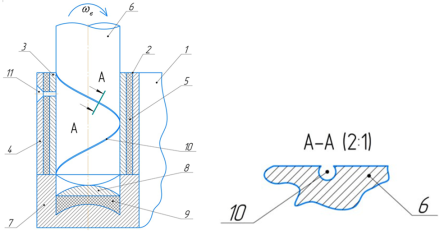
Figure 1. Support structure of the working body for a vertical shaft machine.
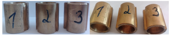
Figure 2. Inner bushing of the working body support structure for a vertical shaft machine.
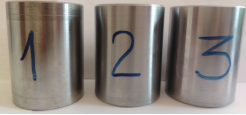
Figure 3. Outer bushing of the working body support structure for a vertical shaft machine.
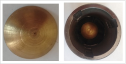
Figure 4. Spherical surface under the base plate of the working body support structure for a vertical shaft machine.
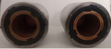
Figure 5. Sliding support bearing assembly.
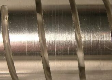
Figure 6. Shaft with helical grooves.
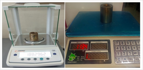
Figure 7.
Load testing of the existing and improved shaft supports.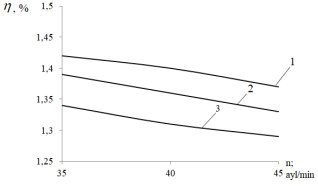
Figure 8. Relationship between shaft rotational speed and wear rate of the inner bushing in the improved working body shaft support structure.
Figure 9. Dependence of wear rate of the improved working body shaft support structure on the helix angle of the groove on the shaft.
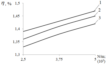
Figure 10. Dependence of wear rate of the improved working body shaft support structure on the stiffness coefficient of its elastic element.
Information


