Abstract
This paper presents an in-depth exploration of control state-space modeling tailored for high-power isolated dual output DC-DC (ISO-D2) converter, with a particular emphasis on elucidating system dynamics through the derivation of state-space matrices and transfer functions. Employing state-of-the-art analysis techniques, this study offers a systematic framework for comprehending the converter's behavior across varied operational scenarios. Through the derivation of state-space matrices encompassing state, input, and output parameters, the converter's dynamic response is encapsulated in a precise mathematical representation. Additionally, transfer functions are established to facilitate frequency domain analysis and stability evaluation. These derived models furnish invaluable insights into the performance characteristics of the converter, thus enabling the formulation of robust control strategies. Particularly, the derived state-space matrices and transfer functions serve as instrumental tools for the design of advanced control algorithms, crucial for optimizing the performance of high-power isolated dual output DC-DC (ISO-D2) converters, in real-world applications such as solar plants and offshore DC wind farms.
1. Introduction
Designing effective control strategies for high-power isolated dual output DC-DC DC-DC (ISO-D2) converters presents unique challenges due to their complex dynamics and strict performance demands
| [1] | Y. Liao, H. Wu, X. Wang, M. Ndreko, R. Dimitrovski and W. Winter, "Stability and Sensitivity Analysis of Multi-Vendor, Multi-Terminal HVDC Systems," IEEE Open Journal of Power Electronics, vol. 4, pp. 52-66, 2023. https://doi.org/10.1109/OJPEL.2023.3234803 |
[1]
. High-power converters, especially in applications such as offshore wind energy systems or interplanetary spacecraft power systems, operate under varying load and environmental conditions. These systems require precise control mechanisms to ensure stability and responsiveness, as they exhibit multi-dimensional dynamics influenced by factors such as voltage, frequency, and load variations
| [2] | G. Sarfi and O. Beik, "High Voltage Wind Turbine Conversion System with Dual DC Converter for MVDC Grids," 2023 IEEE Energy Conversion Congress and Exposition (ECCE), Nashville, TN, USA, 2023, pp. 563-567. https://doi.org/10.1109/ECCE53617.2023.10361992 |
[2]
. Achieving reliable control under these conditions is best approached through state-space modeling techniques, which provide a robust framework for representing system dynamics via state variables, inputs, and outputs
| [1] | Y. Liao, H. Wu, X. Wang, M. Ndreko, R. Dimitrovski and W. Winter, "Stability and Sensitivity Analysis of Multi-Vendor, Multi-Terminal HVDC Systems," IEEE Open Journal of Power Electronics, vol. 4, pp. 52-66, 2023. https://doi.org/10.1109/OJPEL.2023.3234803 |
[1]
. This approach enables insights into converter behavior across diverse conditions, facilitating stability analysis that is crucial for robust control system design
| [3] | A. Stan, S. Costinaș, and G. Ion, “Overview and Assessment of HVDC Current Applications and Future Trends,” Energies, vol. 15, no. 3, p. 1193, Feb. 2022. https://doi.org/10.3390/en15031193 |
[3]
.
In ISO-D2 converters, state-space modeling captures essential voltage and current dynamics, control actions, and disturbances
| [3] | A. Stan, S. Costinaș, and G. Ion, “Overview and Assessment of HVDC Current Applications and Future Trends,” Energies, vol. 15, no. 3, p. 1193, Feb. 2022. https://doi.org/10.3390/en15031193 |
[3]
. Notably, it allows for analyzing eigenvalues of state-space matrices, enabling engineers to assess stability across different operating conditions and ensuring resilience against uncertainties and disturbances
| [4] | P. T. Huynh, P. J. Wang and A. Banerjee, "An Integrated Permanent-Magnet-Synchronous Generator–Rectifier Architecture for Limited-Speed-Range Applications," IEEE Transactions on Power Electronics, vol. 35, no. 5, pp. 4767-4779, May 2020. https://doi.org/10.1109/TPEL.2019.2946244 |
[4]
. Furthermore, state-space modeling underpins the development of feedback control algorithms specifically tailored to ISO-D2 converters, guiding the design of state feedback controllers that regulate variables to meet stringent performance criteria, including voltage regulation, transient response, and disturbance rejection
| [4] | P. T. Huynh, P. J. Wang and A. Banerjee, "An Integrated Permanent-Magnet-Synchronous Generator–Rectifier Architecture for Limited-Speed-Range Applications," IEEE Transactions on Power Electronics, vol. 35, no. 5, pp. 4767-4779, May 2020. https://doi.org/10.1109/TPEL.2019.2946244 |
[4]
.
Recent advancements in high-voltage DC-DC converters, such as isolated dual-output configurations for medium-voltage DC (MVDC) grids, have introduced new dynamic behaviors that demand adaptive control strategies. Techniques like multi-time scale synchronization and adaptive power-sharing schemes have proven effective in stabilizing power-dense grids dominated by power electronics
| [5] | S. D'silva, M. F. Umar, A. Zare, M. B. Shadmand, S. Bayhan and H. Abu–Rub, "Multi-time Scale Synchronization and Adaptive Power Sharing Control Scheme for Grid Forming Inverters in a Power Electronics Dominated Grid," 2023 IEEE Applied Power Electronics Conference and Exposition (APEC), Orlando, FL, USA, pp. 587-593, 2023. https://doi.org/10.1109/APEC43580.2023.10131216 |
| [6] | A. Imanlou, E. S. Najmi, R. Behkam, M. Nazari-Heris and G. B. Gharehpetian, "A New High Voltage Gain Active Switched-Inductor Based High Step-Up DC–DC Converter with Coupled-Inductor," in IEEE Access, vol. 11, pp. 56749-56765, 2023. https://doi.org/10.1109/ACCESS.2023.3283471 |
[5, 6]
. In scenarios where continuous real-time adjustments are essential, such as spacecraft power distribution, integrated converter control enables seamless transitions across high and low voltage systems, highlighting the critical role of dynamic control for reliable operation
| [7] | G. Sarfi, O. Beik, M. Gholamian and S. Talebzadeh, "Parallel Control of an Electric Power and Propulsion System for an Interplanetary Spacecraft," 2024 IEEE Aerospace Conference, Big Sky, MT, USA, pp. 1-9, 2024. https://doi.org/10.1109/AERO58975.2024.10521437 |
[7]
. This study leverages state-space modeling and adaptive control schemes to explore converter stability and dynamic response, optimizing performance under fluctuating conditions and disturbances
| [2] | G. Sarfi and O. Beik, "High Voltage Wind Turbine Conversion System with Dual DC Converter for MVDC Grids," 2023 IEEE Energy Conversion Congress and Exposition (ECCE), Nashville, TN, USA, 2023, pp. 563-567. https://doi.org/10.1109/ECCE53617.2023.10361992 |
| [5] | S. D'silva, M. F. Umar, A. Zare, M. B. Shadmand, S. Bayhan and H. Abu–Rub, "Multi-time Scale Synchronization and Adaptive Power Sharing Control Scheme for Grid Forming Inverters in a Power Electronics Dominated Grid," 2023 IEEE Applied Power Electronics Conference and Exposition (APEC), Orlando, FL, USA, pp. 587-593, 2023. https://doi.org/10.1109/APEC43580.2023.10131216 |
[2, 5]
. By establishing a foundation in control state-space modeling, this paper supports the development of feedback control strategies tailored to meet the rigorous stability and performance demands of converters in practical applications. The focus of this study is on the ISO-D2 converter introduced in
| [2] | G. Sarfi and O. Beik, "High Voltage Wind Turbine Conversion System with Dual DC Converter for MVDC Grids," 2023 IEEE Energy Conversion Congress and Exposition (ECCE), Nashville, TN, USA, 2023, pp. 563-567. https://doi.org/10.1109/ECCE53617.2023.10361992 |
[2]
, which offers significant benefits for wind farms, such as reducing the costs and maintenance associated with an MVDC stage. This paper provides a comprehensive control study of the converter, emphasizing its practical advantages and efficiency in offshore wind applications.
2. Real World Application and Control Goals
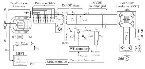
HVDC transmission has gained momentum, but offshore wind farm collector grids, tasked with gathering power from wind turbines (WTs), mostly remain AC-based
| [2] | G. Sarfi and O. Beik, "High Voltage Wind Turbine Conversion System with Dual DC Converter for MVDC Grids," 2023 IEEE Energy Conversion Congress and Exposition (ECCE), Nashville, TN, USA, 2023, pp. 563-567. https://doi.org/10.1109/ECCE53617.2023.10361992 |
[2]
. To harness the advantages of DC systems fully, there's growing interest in shifting collector grids to medium voltage DC (MVDC) systems. Coupled with HVDC transmission, this offers an all-DC solution for offshore wind farms (see
Figure 1). However, the main hurdle has been the reliance on low-voltage WT conversion systems, which are bulky and expensive due to the lack of high-voltage semiconductor devices
| [2] | G. Sarfi and O. Beik, "High Voltage Wind Turbine Conversion System with Dual DC Converter for MVDC Grids," 2023 IEEE Energy Conversion Congress and Exposition (ECCE), Nashville, TN, USA, 2023, pp. 563-567. https://doi.org/10.1109/ECCE53617.2023.10361992 |
[2]
. To tackle this challenge, various solutions, including series-connected WTs and step-up DC-DC converters, have been proposed to increase WT output voltage for MVDC grid connection. In response, this paper introduces a high-voltage WT conversion system comprising a dual-excitation high-voltage generator system, a passive rectification stage, and an isolated dual-output DC-DC converter. Key features include overcoming issues with series-connected WTs, eliminating internal voltage source converters (VSCs), and enabling seamless WT connection to MVDC grids.
Control strategies are vital for effective integration, ensuring smooth operation and optimal performance
| [8] | F Mumtaz, N Zaihar Yahaya, S T Meraj, BnSingh, R Kannan, O Ibrahim, “Review on non-isolated DC-DC converters and their control techniques for renewable energy applications,” Ain Shams Engineering Journal, Volume 12, Issue 4, Pages 3747-3763, ISSN 2090-4479, 2021. https://doi.org/10.1016/j.asej.2021.03.022 |
[8]
. It is also important to minimize mechanical stress on all components, including the generators
| [9] | M Nabavi, A Pourabdol, M Jamal-Omidi. "Numerical study of the effect of the composite patches on the stress intensity factors for a circumferential fully crack in pipes." Journal of Structural and Construction Engineering 7.1, 240-254, 2020. https://doi.org/10.22065/jsce.2018.112332.1415 |
| [10] | D Gee, D Bower, M Bielski, E Mangan, D Schell, K Ghahremani, “Achieving Climate Control with Renewable Energy.” International Mechanical Engineering Congress & Exposition, 2019. https://doi.org/10.1115/IMECE2019-10751 |
[9, 10]
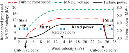
. Different modes of isolated dual output DC-DC (ISO-D2) converter operation is utilized, with the control goal being to provide the demanded voltage as wind velocity varies (see
Figure 2). The benchmark wind farm employs Siemens SWT-3.6-107 turbines, integrated with a proposed scheme for optimized power generation across varying wind speeds. Turbines activate above the cut-in velocity of 4 m/s, reaching rated power at 14 m/s, and then reducing power output beyond the cut-out velocity of 25 m/s, with blade feathering for gust protection. The ISO-D2 converter steps up variable voltages from 6.7 kV to 18.5 kV for the MVDC grid and further to 150 kV for transmission. Maximum power point tracking (MPPT) and wound field (WF) current injection are controlled by the main and auxiliary circuits, respectively, enabling turbine activation across wind speed ranges.
Figure 1. Proposed all-DC system for wind conversion system.
3. Converter Physical Behavior
3.1. Operating Modes
The
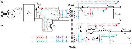
Figure 3 shows the ISO-D2 topology while identifying different conversions within the converter. The first conversion is DC-AC that is formed by the switch S1 and the magnetizing inductor (Lm) as a temporary storage. The high-frequency AC is then transferred to the two outputs (by turns ratio of n2/n1 and n3/n1), where in the main output it is rectified (Ds) and filtered (Cs) before connecting to MVDC grid. In the auxiliary output after rectification and filtering (Dt, Ct) the voltage is further stepped down (S2, Db, Lb) and filtered (Cb) before connection to the TEG WF winding. The ISO-D2 converter has four modes of operations as illustrated in
Figure 3. Mode 1 (Switches S1: ON, S2: ON): Lm is energized in this mode while the opposite polarity of transformer outputs with respect to the primary reverse-biases diodes Ds and Dt blocking the output current flow. The capacitors Cs and Ct, that are charged in other modes of operations, will discharge to their respective output while maintaining the Vmvdc and Vwf voltages, respectively. Note, in this mode the step-down stage of the auxiliary is in operation. Mode 2 (Switches S1: ON, S2: OFF): The operation of ISO-D2 in Mode 2 is similar to that of Mode 1, except for the step-down stage in the auxiliary circuit. Once switch S2 turns OFF the inductor Lb induced voltage due to monetarily current change overcomes the voltage across the Ct hence forward biasing the diode Db. In this mode the energy stored in the Lb is discharged to the auxiliary output. Mode 3 (Switches S1: OFF, S2: ON): Once the switch S1 turns OFF the stored energy in Lm is discharged through the transformer’s primary winding to the output. Diodes Ds and Dt are forward-biased, transferring the energy to their respective output while charging capacitors Cs, Ct, and Cb. In this mode the inductor Lb in the step-down stage is being charged while diode Db is reverse-biased. Mode 4 (Switches S1: OFF, S2: OFF): The operation of converter in this mode is similar to that of Mode 3, however, in the step-down stage as switch S2 turns OFF the diode Db is forward-biased and the inductor Lb will be discharged to the auxiliary output
| [2] | G. Sarfi and O. Beik, "High Voltage Wind Turbine Conversion System with Dual DC Converter for MVDC Grids," 2023 IEEE Energy Conversion Congress and Exposition (ECCE), Nashville, TN, USA, 2023, pp. 563-567. https://doi.org/10.1109/ECCE53617.2023.10361992 |
[2]
.
Figure 3. ISO-D2 converter modes of operation.
3.2. Design Limitations
DC-DC converters operate in either continuous conduction mode (CCM) or discontinuous conduction mode (DCM). In DCM, the inductor current drops to zero during part of the switching cycle, often when the load is light. CCM ensures the inductor current never falls to zero, maintaining continuous energy transfer. It's preferred for its efficiency, regulation, and reduced interference. Components in the converter must be designed to keep it in CCM, analyzed based on capacitor voltage and inductor current.
4. Control Study of ISO-D2
4.1. Open-loop Model
In an electric circuit, the dynamic behavior of electric systems is primarily influenced by the changing values of inductor currents and capacitor voltages. Thus, in our system, considering variables Vmvdc, Vwf, Vct and iLm, iLb is essential for accurately deriving the model, necessitating the calculation of their derivatives. The behavior of power electronic circuits also varies across different modes of operation due to the presence of switches (refer to section 3. A for details). Therefore, to establish the mathematical model of this system, it is necessary to derive the system's average behavior over all modes of operation within one switching period
| [12] | C. Shah et al., "Review of Dynamic and Transient Modeling of Power Electronic Converters for Converter Dominated Power Systems," in IEEE Access, vol. 9, pp. 82094-82117, 2021. https://doi.org/10.1109/ACCESS.2021.3086420 |
[12]
. In this circuit, Vct = n3/n2 Vmvdc. Consequently, Vct is not an independent variable and does not necessitate inclusion in the control study. In this circuit, as can be seen from
Figure 4, Vct= n3/n2 Vmvdc.
Referring to
Figure 4, in mode 1 the following equations can be derived:
(2)
(3)
(4)
In mode 2, (
1), (
2) and (
4) are held, but the equation (
3) for iLb changes to:
In mode 3, (
3) and (
4) are held, but the equations (
1) for iLm and (2
) Vmvdc change to:
(6)
(7)
In mode 4, (
1)-(
4) are held.
By taking the average of variables’ derivatives over one switching period, the linearized average models of the variables are obtained as follows:
(8)
(9)
(10)
(11)
4.2. Linearized Open-loop Model
As demonstrated in previous section, the equations derived for the state variables of this system are nonlinear and vary according to different switching patterns. At this juncture, considering an operating point (O.P.) becomes imperative for two reasons: first, to determine which switching pattern the system encounters, and secondly, to identify the point around which the system needs to be linearized. We designate the rated O.P. as the chosen one (
Table 1). This choice aligns with the system to operate predominantly at this point to achieve optimal efficiency. At this O.P., with d2 greater than d1, we identify equations (
8)-(
11) as representing the nonlinear system. Subsequently, we proceed by computing the Jacobian matrix and applying the operational point (O.P.) outlined in
Table 1. This process yields equations (
12) from (
8) to (
11).
The linearized state-space model around the introduced O.P. is expressed as:
,,
where, x is the vector of control (state) variables, u is the vector of inputs, y is the vector of outputs, and A, B are the matrices of a linearized system. The parameters marked by asterisk (*) are equal to their steady-state values in
Table 1.
The system representation in transfer matrix form around the desired O.P. is as (
13).
=
=
=(13)
Table 1.
Rated operating point specifications | [2] | G. Sarfi and O. Beik, "High Voltage Wind Turbine Conversion System with Dual DC Converter for MVDC Grids," 2023 IEEE Energy Conversion Congress and Exposition (ECCE), Nashville, TN, USA, 2023, pp. 563-567. https://doi.org/10.1109/ECCE53617.2023.10361992 |
Unit | Value |
Wind velocity (m/s) | 15 |
Magnetizing inductor current (ave. A) | 400 |
Rectified voltage (kV) | 18.5 |
ISO-D2 main equivalent resistor (Ω) | 95.07 |
ISO-D2 main voltage (ave. kV) | 18.5 |
ISO-D2 main current (ave. A) | 194.3 |
ISO-D2 aux. equivalent resistor (Ω) | 0.078 |
WF/ISO-D2 aux.voltage (ave. V) | 37.93 |
WF/ISO-D2 aux.current (ave. A) | 486.23 |
(p.u.) | 0.5 |
(p.u.) | 1 |
5. Control Design and Simulation
The following equations provide a framework for analyzing and designing controllers for dynamic systems. The matrices Nrepresent the system dynamics, while the control law matrices K and L will be designed to achieve desired control objectives.
5.1. Linear System Analysis
Finding the eigenvalues of matrix A in (
12) reveals that the linearized open-loop system model is stable around the selected operating point, as indicated by the condition where the real part of all the eigenvalues are negative (as can be seen in (14)).
(15)
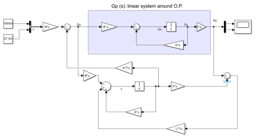
In order to determine estimate and controller poles, the linear system is simulated in MATLAB as
Figure 4.
Figure 4. Linear system simulation scheme.
In simulation coefficients i and j are used for K and L, and by applying try and effort the value of the estimator and controller matrix are resulted as follows:
(16)
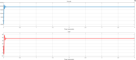
The simulation result based on determined K and L are as follows which shows the effectiveness of controller as the voltage match desired values.
Figure 5. Simulation results for linear system.
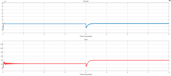
5.2. Non-linear System Analysis
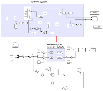
The major difference for nonlinear systems is that the circuit of the converter is used for the simulation scheme as
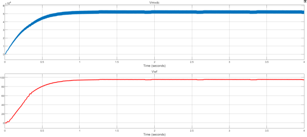
Figure 6. For nonlinear system first the same values linear system is used for K and L and the simulation results (see
Figure 7) shows the system does not follow desired values and the controller need to be modified.
Figure 6. Non-linear system simulation scheme.
Figure 7. Simulation results for non-linear system.
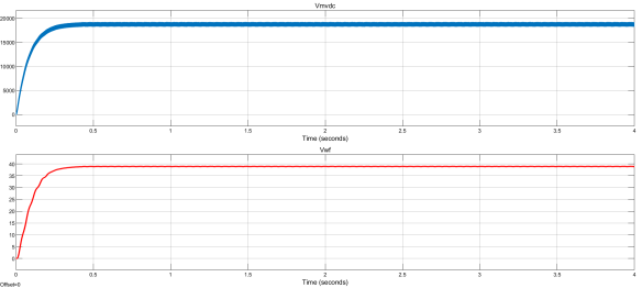
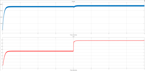
Hence, the same approach as the linear system is applied for the nonlinear system K and L redetermination, and K and L are resulted as follows:
(17)
The simulation result based on the determined K and L are as
Figure 8 which shows the effectiveness of the controller as the voltage matches desired values.
Figure 8. Simulation results for linear system.
5.3. Gain Scheduling
In order to apply gain scheduling to improve controller performance, two different operating point are considered, and three different scenarios are tested to better understand the behavior of system and conclude the best performance.
Table 2. Operating Points for Gain Scheduling.
Simulation Time | 0-4 s | 4-8 s |
Wind velocity | 7 m/s | 15 m/s |
D1 | 0.49 | 0.5 |
D2 | 0.6 | 1 |
Rectified voltage (kV) | 13.19 | 18.5 |
ISO-D2 main power (MW) | 0.8 | 3.6 |
WF/ISO-D2 aux.voltage (ave. V) | 22.99 | 37.93 |
ISO-D2 main voltage (ave. kV) | 18.5 | 18.5 |
Scenario 1: two O.P. without gain scheduling and L=K.
Figure 9. Simulation results for scenario 1.
Scenario 2: two O.P. without gain scheduling with L faster than K.
Figure 10. Simulation results for scenario 2.
Scenario 3: two O.P. with gain scheduling with L faster than K, N= [0.0007/18500 0; 0 0.0005].
Figure 11. Simulation results for scenario 3.
As can be seen in
Figure 9 to
Figure 11, the transient time improved and the ripple in WF voltage decreased.
The linear system analysis in effectively establishes the stability of the dual-output DC-DC converter model by focusing on the linearized system around a carefully selected operating point. By examining the eigenvalues of matrix A, we confirm that the linearized open-loop model is stable, as indicated by the negative real parts of these eigenvalues. This method, applied through MATLAB simulations, demonstrates that the control strategy achieves desired voltage levels and performs reliably under set conditions, underscoring the controller's effectiveness for steady-state operations.
While this method is suitable for linearized system behavior at specific points, enhancing the converter's robustness and flexibility could benefit from more advanced techniques. Future studies might explore Sliding Mode Control (SMC) to manage system nonlinearities and improve disturbance rejection capabilities, making the system more resilient to the variable conditions encountered in offshore environments
| [13] | Y. Mousavi, G. Bevan, I. B. Kucukdemiral and A. Fekih, "Observer-Based High-Order Sliding Mode Control of DFIG-Based Wind Energy Conversion Systems Subjected to Sensor Faults," in IEEE Transactions on Industry Applications, vol. 60, no. 1, pp. 1750-1759, Jan.-Feb. 2024. https://doi.org/10.1109/TIA.2023.3317823 |
[13]
. Additionally, adopting Multi-Agent Control in Singular Systems could facilitate coordinated control across multiple wind turbines or converter modules, addressing the complex interactions within a large-scale offshore wind farm
| [14] | F. Zarei and B. Shafai, "Consensus of Multi-Agent Singular Systems by Using an Algebraic Transformation," 2024 32nd Mediterranean Conference on Control and Automation (MED), Chania - Crete, Greece, pp. 682-687, 2024. https://doi.org/10.1109/MED61351.2024.10566145 |
[14]
. These advanced strategies could complement the existing method, broadening the converter's adaptability and optimizing its performance across a broader range of operating scenarios.
6. Conclusions
The In conclusion, the study addresses the intricate task of designing effective control strategies for high-power isolated dual output DC-DC (ISO-D2) converters, which are essential components in various applications, including offshore wind farm collector grids transitioning to medium voltage DC (MVDC) systems. By utilizing state-space modeling techniques, the paper offers insights into the complex dynamics of ISO-D2 converters, facilitating stability analysis and control algorithm design tailored to meet performance criteria such as voltage regulation, transient response, and disturbance rejection. The proposed high-voltage WT conversion system, comprising a dual-excitation high-voltage generator system, a passive rectification stage, and an isolated dual-output DC-DC converter, addresses challenges associated with low-voltage WT conversion systems and enables seamless integration with MVDC grids. The study demonstrates the effectiveness of control strategies through mathematical modeling, simulation, and gain scheduling techniques, highlighting the importance of robust control for optimizing system operation and performance in real-world applications.