Abstract
The article approaches in a comparative way the series and parallel connection of flat solar collectors using glass covers, creating a low-cost, easy-to-assemble solar thermal system in the Heróis Mozambicanos neighborhood, in the city of Chimoio. The thermal efficiency of each collector and each connection made in the solar collectors was analyzed. These solar collectors have good outlet temperatures, as they can heat water to the recommended ideal temperature, which is above 30°C. Therefore, this article approaches the use of solar energy using low-cost systems that are accessible to the population, built with materials that are easily found in the national market, for basic purposes. To carry out this article, the experimental method was used, which consisted of producing two prototypes of solar collectors. In addition to the experimental method, a bibliographic analysis technique was used, which consisted of gathering information in books, dissertations, websites, and manuals already published on the subject. For data collection, opted to use a TPM-10 digital thermometer, which consisted of viewing temperature data, and a cell phone stopwatch to measure the time spent during the time intervals under study. Microsoft Office Excel was used for data analysis, and temperature data obtained on instruments during the study was used to determine thermal efficiency, yield, useful power, and global solar radiation. With the solar water heating system, such as the flat solar collectors developed, good temperature indices were obtained, between 37.7°C and 68.1°C, with a thermal efficiency of 52.9%. Meanwhile, conventional solar collectors sold on the domestic market and some installed on hospital roofs typically have a thermal efficiency of over 55%.
|
Published in
|
Journal of Energy and Natural Resources (Volume 14, Issue 3)
|
|
DOI
|
10.11648/j.jenr.20251403.13
|
|
Page(s)
|
101-117 |
|
Creative Commons
|

This is an Open Access article, distributed under the terms of the Creative Commons Attribution 4.0 International License (http://creativecommons.org/licenses/by/4.0/), which permits unrestricted use, distribution and reproduction in any medium or format, provided the original work is properly cited.
|
|
Copyright
|
Copyright © The Author(s), 2025. Published by Science Publishing Group
|
Keywords
Solar Energy, Solar Collectors, Series Connection, Parallel Connection
1. Introduction
Solar radiation is renewable and abundant in our country. Using the solar thermal energy, can be reduce electricity consumption and contribute to sustainability. With the use of alternative and inexpensive materials such as solar collectors, even if they are not highly efficient, this technology can become more popular and help spread the culture of using renewable energy sources, furthermore, explore the use of solar energy, which is abundant in our country.
Electric showers consume a lot of energy to heat water, which could be supplied by solar energy, reducing the need for other energy sources that are more expensive and pose greater environmental and social risks. Thus, the use of solar heaters, such as flat plate solar collectors, is excellent for reducing electricity consumption and benefiting the hot water generation and distribution system
| [11] | MENDES, Bárbara de Morais. Estudo da influência de parâmetros de projeto no desempenho de coletoressolares planos. Departamento de engenharia de controle e automação e técnicas fundamentais. Universidade federal de ouro preto – ufop escola de minas. Ouro preto - mg 2017. |
[11]
.
As a way of making hot water production in flat plate solar collectors more efficient, this study aims to analyze the use of flat plate solar collectors connected in series and in parallel in reducing hot water loss and increasing thermal efficiency. To this end, the series and parallel connection of solar collectors were evaluated comparatively.
Flat solar collectors are economical compared to concentrating collectors and vacuum tube collectors. They offer good value for money and have multiple mounting options, making installation simple. These characteristics, combined with the need to produce hot water using several flat solar collectors, make it easy to study the connection of flat solar collectors in parallel as well as in series.
The comparative study of flat solar collectors configured in series and in parallel for hot water consumption was considered pertinent because studying these connections will help society with methods of producing hot water using low-cost materials, the most effective connections according to the producer's needs, assembly options and economic conditions. The study benefits in the thermal analysis of the efficiency and yield of hot water produced in series and parallel connections of flat solar collectors and analysis of climatic conditions for good performance according to their connections.
The study is focused on the development of flat solar collectors configured in series and in parallel to compare performance and thermal efficiency, specifically:
1) Describe the series and parallel connections of flat solar collectors;
2) Construct flat solar collectors configured in series and in parallel;
3) Analyze the thermal efficiency and performance of flat solar collectors configured in series and in parallel.
2. Literary Review
2.1. Solar Energy
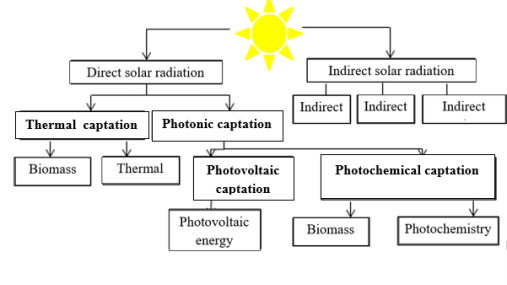
Solar energy is one of the most important forms of renewable energy in existence, since almost all other forms of energy, such as ocean energy, biomass, wind and fossil fuels, are indirect forms of solar energy. Solar energy can be transformed into two main types: solar thermal energy and solar electrical energy. The main applications of solar thermal energy to be dealt with in this work are the heating of domestic hot water in buildings for collective and residential use, for which solar collectors are used
| [2] | CERVEIRA, Manuel. Sistemas Térmicos de Energia Solar. Departamento de Engenharia Eletrotécnica. Trabalho de Projecto apresentado para a obtenção do grau de Mestre em Automação e Comunicações em Sistemas de Energia. Coimbra, Dezembro 2012. |
[2]
.
Solar energy is by far the most attractive alternative energy source for the future because, in addition to its non-polluting characteristics, the amount of energy available for conversion is equivalent to several times the world's current consumption
| [2] | CERVEIRA, Manuel. Sistemas Térmicos de Energia Solar. Departamento de Engenharia Eletrotécnica. Trabalho de Projecto apresentado para a obtenção do grau de Mestre em Automação e Comunicações em Sistemas de Energia. Coimbra, Dezembro 2012. |
[2]
.
2.1.1. Solar Radiation
Solar radiation is short-wave electromagnetic energy that reaches the earth after being partially absorbed by the atmosphere. The greatest influence of solar radiation is on the distribution of the planet's temperature. The amount of radiation varies according to the time of year and latitude
| [5] | FROTA, A. B; SCHIFFER, S. T. R. Manual de conforto térmico. 5. ed. São Paulo, Studio Nobel, 2001, 243p. ISBN 85-85445-39-4. |
[5]
.
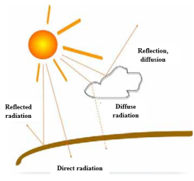
Solar radiation has several components: direct solar radiation E
dir from the sun, which reaches the earth without any change in direction, and diffuse radiation Ed
if, which reaches the observer's eyes through the diffusion of air molecules and dust particles. Diffuse radiation also includes radiation reflected by the Earth's surface. The sum of diffuse and direct radiation is equivalent to global solar radiation E
G | [2] | CERVEIRA, Manuel. Sistemas Térmicos de Energia Solar. Departamento de Engenharia Eletrotécnica. Trabalho de Projecto apresentado para a obtenção do grau de Mestre em Automação e Comunicações em Sistemas de Energia. Coimbra, Dezembro 2012. |
[2]
.
Global solar radiation is the radiant energy per unit of time and area incident on a surface, expressed in W/m2/day, given by the sum of its direct and diffuse components. It can be measured by different instruments, being one of the most widely used parameters for measuring this radiation component.
2.1.2. Solar Thermal Systems
The objective of solar thermal systems is to supply a substantial part of the energy needs for domestic hot water (DHW) in all the fractions of the house, using solar radiation. These systems need to be known both in terms of possible designs and the equipment and accessories that make them up
| [13] | NOVAIS; Marisa Sofia Teixeira. Energias Renováveis e Eficiência Energética. Escola Superior de Tecnologia e Gestão Instituto Politécnico de Bragança, Junho de 2014. |
[13]
.
2.1.3. Converting Solar Energy into Thermal Energy
In order to convert solar energy, which is available in the form of solar radiation, into thermal energy, a device capable of capturing solar radiation and transferring the energy to a transfer fluid is used. The device in question is the solar collector, which is the central and most economically important element in an installation for capturing solar energy to heat water
| [12] | MIRANDA, Marco António Cunha. Optimização de sistemas solares térmicos. Dissertação submetida para satisfação parcial dos requisitos do grau de mestre em engenharia civil — especialização em construções civis. Julho de 2008. |
[12]
.
2.2. Solar Collectors
A solar collector is a device that absorbs solar energy and transforms it into thermal energy, heating the fluid in the equipment. This fluid can be air, water or another thermal fluid
| [16] | COELHO, Daniel Moreira. Identificação de variáveis críticas e simulação do uso de coletoressolares em prédios residenciais. Rio de Janeiro: Universidade Federal do Rio de Janeiro, 2011. |
[16]
.
According to
| [4] | DUFFIE, John A.; BECKMAN, William A. Solar Engineering of Thermal Processes. New York: John Wiley& Sons, 1991. |
[4]
, solar collectors must have high transmissivity and absorptivity of solar radiation. They lose energy through convection and radiation, and it is desirable that the surface emittance is as low as possible to reduce radiation losses.
Solar collectors are the central components of solar thermal energy installations. Their function is to capture and convert sunlight (short-wave radiation) into heat and transfer the energy obtained with minimal losses to the rest of the system, usually through water, oil or another fluid depending on the system's operating temperature
| [2] | CERVEIRA, Manuel. Sistemas Térmicos de Energia Solar. Departamento de Engenharia Eletrotécnica. Trabalho de Projecto apresentado para a obtenção do grau de Mestre em Automação e Comunicações em Sistemas de Energia. Coimbra, Dezembro 2012. |
[2]
.
They base their operation on two natural phenomena:
1) The absorption of heat by dark surfaces;
2) The upward movement of liquid fluids in circuits with temperature variations.
According to
| [11] | MENDES, Bárbara de Morais. Estudo da influência de parâmetros de projeto no desempenho de coletoressolares planos. Departamento de engenharia de controle e automação e técnicas fundamentais. Universidade federal de ouro preto – ufop escola de minas. Ouro preto - mg 2017. |
[11]
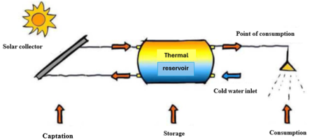
, three systems are needed to heat water: the collection system, consisting of the collector and the pipes that connect the collector to the reservoir; the storage system, which has the thermal reservoir and the auxiliary systems; and finally, the consumption system, which consists of distributing the heated water for final consumption.
Figure 3 illustrates a solar collector heating system.
2.2.1. Types of Collectors
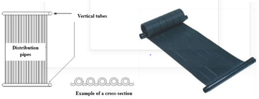
1) Flat collectors without a cover
These collectors briefly comprise plastic tubes (polypropylene, polycarbonate or polyvinyl), placed in the shape of a mat and joined by two larger diameter tubes at the top and bottom. In economic terms, they are more affordable than roofed collectors, although the return on investment is quite similar, as they are less efficient and a larger catchment area is required
| [12] | MIRANDA, Marco António Cunha. Optimização de sistemas solares térmicos. Dissertação submetida para satisfação parcial dos requisitos do grau de mestre em engenharia civil — especialização em construções civis. Julho de 2008. |
[12]
.
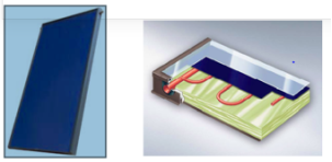
2) Flat collectors with a cover
This is the most conventional type of collector, consisting of an absorber surface, fixed in a watertight box, with a transparent cover, usually made of glass, which, due to the greenhouse effect, reduces thermal losses. This type of solar collector can work efficiently all year round. With the absorber plate painted matte black, maximum operating temperatures of around 50ºC can be reached (within the usual temperature range used for hot water), with good performance
| [12] | MIRANDA, Marco António Cunha. Optimização de sistemas solares térmicos. Dissertação submetida para satisfação parcial dos requisitos do grau de mestre em engenharia civil — especialização em construções civis. Julho de 2008. |
[12]
.
With the so-called selective coatings, temperatures of around 60 to 70ºC can also be achieved with good performance, reducing heat loss through radiation. These absorber plate coatings are obtained through electrochemical treatment or sputtering, which gives the plate optical properties that reduce the emission of infrared radiation while maintaining its high absorption capacity, like black paint
| [12] | MIRANDA, Marco António Cunha. Optimização de sistemas solares térmicos. Dissertação submetida para satisfação parcial dos requisitos do grau de mestre em engenharia civil — especialização em construções civis. Julho de 2008. |
[12]
.
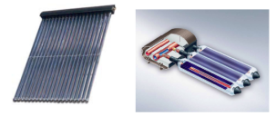
3) Vacuum tube collectors
For slightly higher operating temperatures (<120ºC) with good efficiency, it is already necessary to use vacuum collectors. Inside these collectors, which are usually tubular, air is extracted in order to almost completely reduce heat loss by convection and conduction from the absorber plate
| [12] | MIRANDA, Marco António Cunha. Optimização de sistemas solares térmicos. Dissertação submetida para satisfação parcial dos requisitos do grau de mestre em engenharia civil — especialização em construções civis. Julho de 2008. |
[12]
.
2.2.2. Type of Circulation (Most Commonly Used Classification)
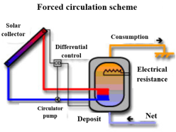
1) Forced circulation
The operation of a forced circulation system is characterized by the existence of a circulating electric pump with the aim of forcing the transfer fluid to circulate in the collectors. The electric pump is controlled by a differential control system that reacts to the temperature difference between the water leaving the collectors and the temperature of the water in the lowest part of the tank, normally 5ºC. When this value is reached, the electric circulator pump is activated and the heat transfer fluid in the collector circulates to the water storage tank, where the heat is transferred to the water via a heat exchanger
| [12] | MIRANDA, Marco António Cunha. Optimização de sistemas solares térmicos. Dissertação submetida para satisfação parcial dos requisitos do grau de mestre em engenharia civil — especialização em construções civis. Julho de 2008. |
[12]
.
In short, in addition to the solar collector, a solar system consists of a storage tank, electric circulator pump, primary circuit, heat exchanger, expansion vessel, air vent, safety valve and conventional energy support equipment
| [12] | MIRANDA, Marco António Cunha. Optimização de sistemas solares térmicos. Dissertação submetida para satisfação parcial dos requisitos do grau de mestre em engenharia civil — especialização em construções civis. Julho de 2008. |
[12]
.
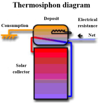
2) Natural circulation (or thermosiphon)
The thermosiphon system generally consists of a set of collectors connected to a well-insulated tank positioned at a higher level than the collectors. No electric circulating pumps are needed, as circulation is carried out by natural convection, induced by the difference in density between the hot and cold water. The water in the collector becomes less dense as it is heated, moving to the top of the circuit, inside the tank. The colder, denser water moves to the lower part of the circuit, at the entrance to the collector. Once in the collector, the cycle begins again and circulation continues as long as there is solar radiation. The circulation flow rate increases as the intensity of solar radiation increases and the water to be used is taken from the top of the solar tank (
Figure 8)
| [12] | MIRANDA, Marco António Cunha. Optimização de sistemas solares térmicos. Dissertação submetida para satisfação parcial dos requisitos do grau de mestre em engenharia civil — especialização em construções civis. Julho de 2008. |
[12]
.
As a rule, the tank should be located above the collector to prevent an inverted thermosiphon effect during the night, which can be avoided by using a non-return valve. These simple systems consist of a solar collector, tank, air vent, expansion vessel, and other small accessories
| [12] | MIRANDA, Marco António Cunha. Optimização de sistemas solares térmicos. Dissertação submetida para satisfação parcial dos requisitos do grau de mestre em engenharia civil — especialização em construções civis. Julho de 2008. |
[12]
.
2.2.3. Connection of Solar Thermal Collectors
As a general rule, for uniform flow distribution, all rows of collectors must have the same number of collectors to ensure equal load losses in all of them, without increasing the cost of accessories
| [8] | LEBENA, Eduardo Pérez; COSTA, Jorge Cruz. Conversão térmica da energia solar. Portugal. |
[8]
.
According to
, the collection subset consists of the collectors and their fasteners and accessories, and is responsible for capturing incident solar energy and transforming it into thermal energy. The collector field comprises the physical space in which they are installed, including the areas that must be left free to avoid shadows and facilitate maintenance. Collectors can be connected in three ways: in parallel, in series, and in a mixed connection (series-parallel).
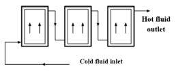
1) Parallel connection
The normal thing is to place the collectors coupled to each other in parallel, forming rows or batteries that are also interconnected in parallel. This solution is most commonly used in DHW and swimming pool heating applications. Collectors can be connected in parallel if they have four connection sleeves or less
.
Connecting the collectors in parallel provides greater performance, but also increases the length and diameter of the pipes, since the total flow is the sum of the flows of all the collectors, which means that the power of the pump to be installed is greater, as is the amount of heat transfer fluid in the circuit, consequently increasing thermal losses. The number of accessories also increases, so the installation cost increases
.
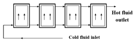
2) Series connection
In this case, the circulation flow rate is the same in all collectors.
Figure 10 shows how the series connection is made.
In this type of connection, the hot heat transfer fluid outlet from the previous collector is connected to the cold heat transfer fluid inlet of the next collector. The fluid will enter the coil through the inlet of the first collector and exit through the outlet of the last collector
.
Each input in the queue will be connected to the lower connection of the first collector and the output to the upper connection of the last collector in the line. To determine the maximum number of collectors that can be connected in series, it is necessary to take into account that the temperature in the last ones may be high and cause damage to the materials or the formation of steam in the circuit. On the other hand, there is a marked drop in performance in the last collectors in series
| [8] | LEBENA, Eduardo Pérez; COSTA, Jorge Cruz. Conversão térmica da energia solar. Portugal. |
[8]
.
The series connection allows for lower flow rates than the parallel connection, smaller pipe sections, and shorter lengths, reducing installation and maintenance costs. The pump to be installed will also have lower power, as the flow rate is lower
.
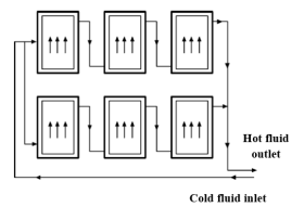
3) Mixed connection
The parallel connection of series collector groups or series groups of parallel collector groups is called mixed. This system is not common and is only used in installations with a very large collection surface area and where temperature requirements are also high, as it reduces the diameter of the pipes to be installed, thereby reducing their cost
.
There is no limit to the number of batteries in this configuration, provided that the hydraulic balance is maintained and the limit on batteries connected in series is respected. This type of assembly should be used in forced circulation systems
| [7] | KISOLTEC. Aquecedor solar. Manual de instalação do aquecedor solar. Brazil. 2017. |
[7]
.
The collection subsystem consists of collectors, their supports, anchors, and other accessories, and is responsible for capturing solar energy and transforming it into thermal energy
.
2.3. Determination of Thermal Parameters
It is necessary to determine the fundamental parameters that assist in determining the thermal performance of the solar heater
| [6] | GUERRA; VARELLA. Análise do desempenho térmico de um sistema de aquecimento solar de baixo custo na cidade de Mossoró – RN. 2014. 98 f. Monografia - Graduação em Engenharia de Energia, Universidade Federal Rural do Semi-Árido, Mossoró-RN, 2012. |
[6]
. According to
| [9] | LOPO, Alexandre Boleira. Análise do desempenho térmico de um sistema de Aquecimento solar de baixo custo. Natal-RN, 2010. |
[9]
Apud
| [6] | GUERRA; VARELLA. Análise do desempenho térmico de um sistema de aquecimento solar de baixo custo na cidade de Mossoró – RN. 2014. 98 f. Monografia - Graduação em Engenharia de Energia, Universidade Federal Rural do Semi-Árido, Mossoró-RN, 2012. |
[6]
, these parameters, which refer to the solar collector of the solar water heating system, are: the overall loss coefficient, power loss, and thermal efficiency.
According to
| [6] | GUERRA; VARELLA. Análise do desempenho térmico de um sistema de aquecimento solar de baixo custo na cidade de Mossoró – RN. 2014. 98 f. Monografia - Graduação em Engenharia de Energia, Universidade Federal Rural do Semi-Árido, Mossoró-RN, 2012. |
[6]
, thermal losses in solar collectors are a consequence of the energy captured migrating from the collector to the atmosphere through convection, conduction, and radiation, due to the temperature difference between them.
The power values initially required to determine the Overall Thermal Loss Coefficient are:
1) Power absorbed by the collector (Pabs)
2) Power transferred to the working fluid (Pu)
3) Power lost by the collector (Pp)
2.4. Determining Thermal Efficiency
One of the most important parameters in defining a collector is its efficiency. The greater the difference between the operating temperature and the ambient temperature, the greater the thermal losses, and therefore the lower the amount of useful energy that the fluid will be able to extract. Depending on the type of collector, efficiency decreases more or less sharply with temperature
| [12] | MIRANDA, Marco António Cunha. Optimização de sistemas solares térmicos. Dissertação submetida para satisfação parcial dos requisitos do grau de mestre em engenharia civil — especialização em construções civis. Julho de 2008. |
[12]
.
When selecting the right collector in terms of performance, the choice is more related to adaptability of function of highest performance value. The thermal performance of the solar collector allows the amount of energy that the system can retain to be determined. This thermal performance of the collector can be determined by the relationship between the power transferred to the working fluid, the area of the solar collector exposed to solar radiation, and the incident solar radiation to which the solar collector is exposed
| [6] | GUERRA; VARELLA. Análise do desempenho térmico de um sistema de aquecimento solar de baixo custo na cidade de Mossoró – RN. 2014. 98 f. Monografia - Graduação em Engenharia de Energia, Universidade Federal Rural do Semi-Árido, Mossoró-RN, 2012. |
[6]
.
According to
| [12] | MIRANDA, Marco António Cunha. Optimização de sistemas solares térmicos. Dissertação submetida para satisfação parcial dos requisitos do grau de mestre em engenharia civil — especialização em construções civis. Julho de 2008. |
[12]
, observation of the collector's characteristic curve should show that for typical temperatures of the application for which the collector is intended, it should perform at no less than 40-50%. This option should be considered when selecting equipment.
3. Research Methodology
This chapter presents the methods and procedures used in the preparation of this article. To achieve the objectives of this article, it was necessary to use the experimental method and the bibliographic analysis technique. Therefore, the experimental method consisted of constructing two flat solar collectors to make the connections in series and in parallel. The bibliographic method consisted of searching for information related to the topic, which involved searching for concepts, laws, and phenomena to give the work greater consistency.
3.1. Materials
The choice of materials for the construction of solar collectors greatly influences the efficiency of the proposed devices, therefore the materials listed in
Table 1 were used.
Table 1. Materials used in the construction of collectors.
No | Materials | Image of the material | Quantity |
1 | PVC pipes, IPS with section ½ | 
| 5 |
2 | PVC elbows, IPS with section ½ | 
| 7 |
3 | PVC joint pipes, IPS e IRS with section ½ | 
| 30 |
4 | PVC Articulated union, IPS with section ½ | 
| 18 |
5 | PVC Simple union, IRS with section ½ | 
| 4 |
7 | PVC Outlet tap, IPS with section ½ | 
| 1 |
8 | PVC Inlet valve, IPS with section ½ | 
| 1 |
9 | Plywood sheets 84cm x 54cm | 
| 2 |
10 | 20-liter reservoir | 
| 1 |
11 | Wooden shelf for the reservoir, 1 meter high | 
| 1 |
12 | Collector's wooden bookcase | 
| 2 |
13 | Wooden collector box measuring 84cm x 54cm | 
| 2 |
14 | Digital thermometer | 
| 1 |
15 | Black enamel paint | 
| 1 l |
16 | Thread sealer or Sellarosca | 
| 1 |
17 | Teflon tape | 
| 5 |
18 | 4mm glass measuring 0.82m x 0.513m | --------------- | 2 |
19 | pipe fitting | 
| 2 |
20 | Connection union | 
| 28 |
Table 2. Support materials for the construction of collectors.
N | Support material | Function |
1 | Knife | Level the pipes after cutting them. |
2 | Alicante | Remove poorly positioned nails and connect the pipes. |
3 | Star wrench | Serve as a support for smaller pipes when threading. |
4 | Hacksaw blade | Cut the pipes. |
5 | Paintbrush | Help paint the pipes and the entire system. |
6 | Protractor | Help show the angle of inclination. |
7 | Tape measure | Help with measurements. |
8 | Pipe wrench | Help thread the pipes. |
3.2. Construction of Flat Solar Collectors
First, two walls of flat solar collectors were made using wooden boards measuring 84 cm long, 54 cm wide, and 12 cm thick. Next, two 84 cm x 54 cm Unitex sheets were glued and nailed to the bottom of the walls, serving as the base for the collectors, one for each collector, as shown in
Figure 12.
Figure 12. Wooden boxes for solar collectors.
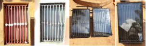
In order to form the water circulation grid, the components were fixed in place, or the pipes were connected to the other elements listed in
Table 1, specifically the tees, elbows, simple joints, articulated joints, and other components, as shown in the figure below. It was then painted black to achieve greater radiation absorption, as shown in
Figure 13.
Figure 13. Connecting the pipes to the solar collector.
Figure 14. Circulation grid painted black.
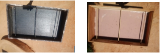
Next, the solar water heater components, the wooden boxes for the solar collectors, and the water circulation grids were installed. All system components were painted black to create a black body. In order to obtain flat solar collectors with a cover, the water inlet and outlet pipes were installed. Next, the glass was fixed and glued to the solar collectors as shown in
Figure 14.
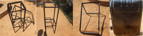
The water tank was also painted black. To ensure that the collectors and the tank are securely supported, racks were built for both the collectors and the tank. The collector racks were built at a 45° angle, in accordance with the literature on efficient use of solar energy.
Figure 15. Solar collector and reservoir racks.
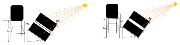
The schematic structures of the systems under study are presented below.
Figure 16. Schematic structure for series and parallel connection.
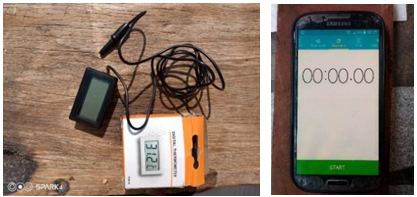
3.3. Data Collection Techniques
In order to measure the water temperature at the inlet and outlet of the collectors, data was collected using observation techniques. Measurements were taken in September 2021, on the 6th, 11th, 12th, 13th, 14th, and 17th. During the hours of highest solar radiation intensity throughout the day, from 9 a.m. to 3 p.m., respectively. The observation was made by observing the temperature and time values provided by the data collection instruments (TPM-10 digital thermometer and Samsung S4 cell phone stopwatch).
Figure 17. Data collection instruments (TPM-10 digital thermometer and Samsung S4 cell phone stopwatch).
3.4. Data Analysis Technique
The data collected on temperature variation was tabulated according to the measurements taken at the times of greatest solar radiation intensity throughout each day, after the test measurements. The thermal efficiency of the solar collectors was then determined based on equation
(
3), using the thermal parameters, specifically: the global solar irradiation (I) according to the study site, the useful power transferred to the working fluid (PU) based on equation
(
4) and the power absorbed by the collector (Pabs) based on equation
(
5). It was also necessary to determine the power lost (Pp) based on equation
(
6), in order to know the reasons for the decrease in thermal efficiency at some points in the system under study. The graphs corresponding to the results inherent in the thermal parameters mentioned above for the analysis of the thermal efficiency of the devices were analyzed using the Microsoft Excel package.
According to the databases of the National Institute of Meteorology of Mozambique (2020), the average annual radiation levels in Mozambique are around 5.6 kWh/m2. In the central region (Chimoio), it is 5.28 kWh/m2.
The solar collector's thermal efficiency allows us to determine how much energy the system can retain. The thermal efficiency of the collector can be determined through the relationship between the power transferred to the working fluid (Pu), the area of the solar collector exposed to solar radiation (A) and the incident solar radiation that the solar collector is exposed to
| [6] | GUERRA; VARELLA. Análise do desempenho térmico de um sistema de aquecimento solar de baixo custo na cidade de Mossoró – RN. 2014. 98 f. Monografia - Graduação em Engenharia de Energia, Universidade Federal Rural do Semi-Árido, Mossoró-RN, 2012. |
[6]
.
Since the study was based on solar collectors, the absorbed power was used in addition to the incident power, since the absorbed power includes the absorption capacity of the plate. According to
| [3] | BEZERRA, A. M. Aplicações térmicas da energia solar. 4. ed. João Pessoa: Universitária, 2001, Cap. 2, p. 47-96. |
[3]
, the absorptivity of the plate (α
P), since it is a black painted plate, is considered to be 0.8.
Where: - Thermal efficiency; Pu - Total useful power transferred to the working fluid in kW; I - Global solar irradiation in kW/m2; A - Collector area (area exposed to solar radiation) in m2; Pabs- power lost.
Power absorbed by the collector (P
abs) - Quantitatively represents the portion of incident energy that is absorbed by the solar collector's absorber plate
| [6] | GUERRA; VARELLA. Análise do desempenho térmico de um sistema de aquecimento solar de baixo custo na cidade de Mossoró – RN. 2014. 98 f. Monografia - Graduação em Engenharia de Energia, Universidade Federal Rural do Semi-Árido, Mossoró-RN, 2012. |
[6]
.
Where: Pabs - is the power absorbed by the collector, in kW; αP - represents the absorptivity of the plate; I - refers to global solar irradiation, in kW/m²; and A - is the area of the solar collector exposed to solar radiation, in m².
Power transferred to the working fluid (Pu) - This power represents the portion of energy that can be transferred to the working fluid, in this case, water
| [6] | GUERRA; VARELLA. Análise do desempenho térmico de um sistema de aquecimento solar de baixo custo na cidade de Mossoró – RN. 2014. 98 f. Monografia - Graduação em Engenharia de Energia, Universidade Federal Rural do Semi-Árido, Mossoró-RN, 2012. |
[6]
.
Where: Pu - represents the useful power transferred to the working fluid, in kW; ṁ - is the mass flow rate, in kg/s; cp corresponds to the specific heat of water, in kJ/kg °C and ΔT - consists of the temperature difference of the fluid obtained in the system, in °C.
Power lost by the collector (P
p) - Portion of the absorbed energy that is lost through the base, sides, and top of the solar collector
| [6] | GUERRA; VARELLA. Análise do desempenho térmico de um sistema de aquecimento solar de baixo custo na cidade de Mossoró – RN. 2014. 98 f. Monografia - Graduação em Engenharia de Energia, Universidade Federal Rural do Semi-Árido, Mossoró-RN, 2012. |
[6]
.
4. Presentation and Analysis of Results
This chapter presented the results regarding the behavior of the devices during operation. The results were obtained during five days of analysis of the proposed solar heaters. The results are necessary to verify the behavior of the water temperature inside the collectors and to ascertain their thermal efficiency.
The solar heaters were made of wood, pipes, and Unitex sheets. Water flows through the pipes as it is heated inside the solar collectors. Inside the collectors are eight (8) interconnected pipes in the shape of a grid, painted black to resemble a black body. The fluid inside is heated by solar radiation that strikes the collector plate, which, through conservation, heats up each time it circulates through the pipes.
Each collector has three holes for pipe entry and exit. The first collector has one hole on the upper left side for water to enter the collectors, coupled with a digital thermometer to measure the temperature of the water entering the collector from the reservoir, and two holes on the right side, one on the upper part and the other on the lower part, which allow the pipes to be connected to those of the next collector. In the second collector, there are two holes on the left side, one at the top and one at the bottom, for connecting the pipes to those of the preceding collector, and one on the right side at the bottom, responsible for the outlet of hot water through a tap, coupled with a digital thermometer to measure the temperature of the water at the solar collector outlet for consumption.
The data was collected between 9:00 a.m. and 3:10 p.m. As can be seen in
Tables 3, 4, 5, 6, 7 and 8, the values are the inlet temperature (Tec), the outlet temperature (Tsc) and the variation between these temperatures (ΔT) in the solar collectors under analysis; the global solar irradiation according to location (I); the useful power transferred to the working fluid (PU); the power absorbed by the collector (Pabs); as well as the result of the thermal efficiency calculation for each solar collector and for each connection. The tables do not include the values for the power lost (Pp), which were determined and used to find out the reasons for the increase and decrease in useful power, which were crucial in obtaining the thermal efficiency.
The following constants were taken into account: the area of each flat solar collector (A1 or A2), in this case 0.45 m², and the total area (AT) of the two solar collectors of 0.9 m2; the mass flow rate (ṁ) of 0.0056 kg/s since the thermal reservoir holds 20 liters of water and the time during one hour of collection, i.e. 3600 seconds; and the specific heat of 4.18 kJ/kg °C.
According to
| [3] | BEZERRA, A. M. Aplicações térmicas da energia solar. 4. ed. João Pessoa: Universitária, 2001, Cap. 2, p. 47-96. |
[3]
, the absorptivity of the plate (α
P), as it is a black painted plate, is considered to be 0.8.
Table 3. Data from the first day for the first collector, ambient temperature 19°C - 30°C (06/09/2021).
Time (h) | Collector | ΔT (°C) | Pu (kW) | Pabs (kW | I (kW/m²) | ηt (%) |
Tec (oC) | Tsc (oC) |
9:00 a.m. - 10:00 a.m. | 24.1 | 50.2 | 26.1 | 0.612 | 1.9008 | 5.28 | 32.2 |
10:02 a.m. - 11:02 a.m. | 25.4 | 54.6 | 29.2 | 0.684 | 1.9008 | 5.28 | 36.0 |
11:04 a.m. - 12:04 p.m. | 26.1 | 63.4 | 37.3 | 0.874 | 1.9008 | 5.28 | 50.0 |
12:06 p.m. - 1:06 p.m. | 26.6 | 62.1 | 35.5 | 0.832 | 1.9008 | 5.28 | 43.8 |
1:08 p.m. - 2:08 p.m. | 25.3 | 56 | 30.7 | 0.720 | 1.9008 | 5.28 | 37.9 |
2:10 p.m. - 3:10 p.m. | 25.8 | 51.2 | 25.4 | 0.595 | 1.9008 | 5.28 | 31.3 |
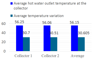
Average | 25.55 | 56.25 | 30.7 | 0.720 | 1.9008 | 5.28 | 37.8 |
Table 4. Data from the 1st day to the 2nd collector, ambient temperature 19°C - 30°C (06/09/2021).
Time (h) | Collector | ΔT (°C) | Pu (kW) | Pabs (kW | I (kW/m²) | ηt (%) |
Tec (oC) | Tsc (oC) |
9:00 a.m. - 10:00 a.m. | 24.1 | 50.8 | 26.7 | 0.626 | 1.9008 | 5.28 | 32.9 |
10:02 a.m. - 11:02 a.m. | 25.4 | 54.9 | 29.5 | 0.691 | 1.9008 | 5.28 | 36.4 |
11:04 a.m. - 12:04 p.m. | 26.1 | 62.7 | 36.6 | 0.858 | 1.9008 | 5.28 | 45.1 |
12:06 p.m. - 1:06 p.m. | 26.6 | 62.3 | 35.7 | 0.837 | 1.9008 | 5.28 | 44.0 |
1:08 p.m. - 2:08 p.m. | 25.3 | 55.3 | 30 | 0.703 | 1.9008 | 5.28 | 37.0 |
2:10 p.m. - 3:10 p.m. | 25.8 | 50.4 | 24.6 | 0.577 | 1.9008 | 5.28 | 30.4 |
Average | 25.55 | 56.06 | 30.51 | 0.715 | 1.9008 | 5.28 | 37.6 |
The data in
Tables 3 and 4 were collected during the same time interval and under the same conditions. Analysis of the results confirmed that the highest temperature reached during the day occurred between 11:04 a.m. and 12:04 p.m. on the first day of analysis, when the first collector reached a temperature of 63.4°C and the second reached a temperature of 62.7°C. It can be seen that the first collector reached a higher temperature than the second collector, but the difference is not very significant, as shown in
Figure 18.
Figure 18. The temperatures of the first and second collectors.
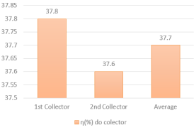
Analyzing the average thermal efficiency of each solar collector, it can be seen that the first collector had a higher thermal efficiency than the second collector, but the difference is not very significant, given that the values are approximate.
Table 5. Data from the first day for parallel connection at an ambient temperature of 16° - 24° (September 11, 2021).
Time (h) | Collector | ΔT (°C) | Pu (kW) | Pabs (kW | I (kW/m²) | ηt (%) |
Tec (oC) | Tsc (oC) |
9:00 a.m. - 10:00 a.m. | 23.2 | 43.3 | 20.1 | 0.471 | 1.9008 | 5.28 | 24.8 |
10:02 a.m. - 11:02 a.m. | 22.8 | 40.2 | 17.4 | 0.408 | 1.9008 | 5.28 | 21.5 |
11:04 a.m. - 12:04 p.m. | 22.3 | 48.8 | 26.5 | 0.621 | 1.9008 | 5.28 | 32.7 |
12:06 p.m. - 1:06 p.m. | 24.5 | 48.7 | 24.2 | 0.567 | 1.9008 | 5.28 | 29.8 |
1:08 p.m. - 2:08 p.m. | 25.1 | 54.1 | 29 | 0.680 | 1.9008 | 5.28 | 35.8 |
2:10 p.m. - 3:10 p.m. | 25.9 | 40.4 | 14.5 | 0.340 | 1.9008 | 5.28 | 17.9 |
Average | 23.96 | 45.91 | 21.95 | 0.515 | 1.9008 | 5.28 | 27.1 |
Table 6. Data from the second day for parallel connection at an ambient temperature of 17° - 27° (September 13, 2021).
Time (h) | Collector | ΔT (°C) | Pu (kW) | Pabs (kW | I (kW/m²) | ηt (%) |
Tec (oC) | Tsc (oC) |
9:00 a.m. - 10:00 a.m. | 24.9 | 56.4 | 31.5 | 0.739 | 1.9008 | 5.28 | 38.9 |
10:02 a.m. - 11:02 a.m. | 25.3 | 58.8 | 33.5 | 0.785 | 1.9008 | 5.28 | 41.3 |
11:04 a.m. - 12:04 p.m. | 26.7 | 63.8 | 37.1 | 0.870 | 1.9008 | 5.28 | 45.8 |
12:06 p.m. - 1:06 p.m. | 25.2 | 68.1 | 42.9 | 1.006 | 1.9008 | 5.28 | 52.9 |
1:08 p.m. - 2:08 p.m. | 27.9 | 64.5 | 36.6 | 0.858 | 1.9008 | 5.28 | 45.1 |
2:10 p.m. - 3:10 p.m. | 28.1 | 51.2 | 23.1 | 0.541 | 1.9008 | 5.28 | 28.5 |
Average | 26.3 | 60.4 | 34.1 | 0.800 | 1.9008 | 5.28 | 42.1 |
Figure 19. The thermal efficiency of the first and second collectors.
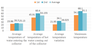
Tables 5 and 6 show the parallel connection data collected on different days and under different weather conditions. On the first day, the ambient temperature ranged from 16°C to 24°C, which made it difficult to heat the water inside the collectors. Under these conditions, the collectors reached a maximum average temperature variation of 21.95°C, from the initial water temperature of 23.96°C, thus reaching an average temperature of 45.91°C for the hot water coming out of the collector. On the second day, the ambient temperature ranged from a minimum of 17°C to a maximum of 27°C, which greatly favored the heating of water in the collectors. Under these conditions, the collectors reached an average variation of 34.1°C, from the initial water temperature of 26.3°C, thus reaching an average hot water temperature of 60.4°C, as shown in
Figure 20.
Figure 20. Average temperatures in parallel connection.
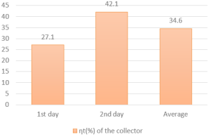
Analyzing the thermal efficiency on the 1st day as shown in
figure 21 in relation to the 2nd day, it can be seen that it was caused by the low water temperatures in the collectors as well as the low ambient temperature. With these climatic conditions inherent to low ambient temperatures on the first day ranging from 16°C to 24°C and on the second day ranging from 17°C to 27°C, the average thermal efficiency achieved by the collectors under these conditions is considered positive. The average thermal efficiency of 42.1% achieved by the collectors on the 2nd day is positive, and is justified by the favorable climatic conditions inherent in the high temperatures on the day under study, as shown in
figure 21.
In addition to the weather conditions, it was observed that on the 1st day the power lost was greater, with a value of 1.3858 kW compared to the 2nd day, with a lower value of 1.1008kW. the thermal efficiency of the 1st day was conditioned by the power losses compared to the 2nd day.
Figure 21. Thermal efficiency average in parallel connection.
The average day's thermal efficiency is viable because it is over 40%. As shown in
figure 21, the thermal efficiency of the days is feasible as it is higher than 30%. These considerations were made due to the low temperatures on the first day of data collection and the high temperatures on the second day.
Table 7. Data from the first day for series connection at an ambient temperature of 18° - 27° (September 14, 2021).
Time (h) | Collector | ΔT (°C) | Pu (kW) | Pabs (kW | I (kW/m²) | ηt (%) |
Tec (oC) | Tsc (oC) |
9:00 a.m. - 10:00 a.m. | 25.2 | 57 | 31.8 | 0.746 | 1.9008 | 5.28 | 39.2 |
10:02 a.m. - 11:02 a.m. | 27.2 | 63.1 | 35.9 | 0.842 | 1.9008 | 5.28 | 44.3 |
11:04 a.m. - 12:04 p.m. | 26.3 | 64.7 | 38.4 | 0.900 | 1.9008 | 5.28 | 47.3 |
12:06 p.m. - 1:06 p.m. | 27.5 | 62.2 | 34.7 | 0.814 | 1.9008 | 5.28 | 42.8 |
1:08 p.m. - 2:08 p.m. | 26.1 | 60 | 33.9 | 0.795 | 1.9008 | 5.28 | 41.8 |
2:10 p.m. - 3:10 p.m. | 26.9 | 52.8 | 25.9 | 0.607 | 1.9008 | 5.28 | 31.9 |
Average | 26.53 | 59.96 | 33.43 | 0.784 | 1.9008 | 5.28 | 41.2 |
Table 8. Data from the second day for series connection at an ambient temperature of 17°C - 25°C (September 17, 2021).
Time (h) | Collector | ΔT (°C) | Pu (kW) | Pabs (kW | I (kW/m²) | ηt (%) |
Tec (oC) | Tsc (oC) |
9:00 a.m. - 10:00 a.m. | 23.1 | 37.7 | 14.6 | 0.342 | 1.9008 | 5.28 | 18.0 |
10:02 a.m. - 11:02 a.m. | 23.7 | 44.4 | 20.7 | 0.485 | 1.9008 | 5.28 | 25.5 |
11:04 a.m. - 12:04 p.m. | 24.8 | 47.2 | 22.4 | 0.525 | 1.9008 | 5.28 | 27.6 |
12:06 p.m. - 1:06 p.m. | 25.6 | 50 | 24.4 | 0.572 | 1.9008 | 5.28 | 30.1 |
1:08 p.m. - 2:08 p.m. | 24.8 | 51.3 | 26.5 | 0.621 | 1.9008 | 5.28 | 32.6 |
2:10 p.m. - 3:10 p.m. | 25.1 | 45.6 | 20.5 | 0.480 | 1.9008 | 5.28 | 25.3 |
Average | 24.5 | 46 | 21.5 | 0.504 | 1.9008 | 5.28 | 26.5 |
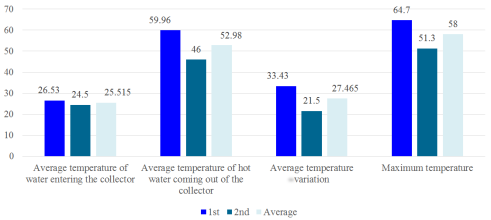
Tables 7 and 8 show the serial connection data collected on different days and under different weather conditions. On the first day, the ambient temperature ranged from a minimum of 18°C to a maximum of 27°C, which greatly favored the heating of water in the collectors. Under these conditions, the collectors reached an average variation of 33.43°C from the initial water temperature to an average temperature of 26.53°C, thus reaching an average temperature of 59.96°C for the hot water coming out of the collector.
On the second day of this connection study, the ambient temperature ranged from a minimum of 17°C to a maximum of 25°C, which made it difficult to heat the water inside the collectors. Under these conditions, the collectors reached a maximum average temperature variation of 21.5°C, from the initial water temperature to 23.96°C, with a total outlet water temperature in the collector of 46°C.
Figure 22. Average temperatures in series connection.
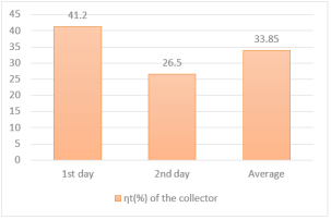
Analyzing the low thermal efficiency on the first day, as shown in the figure below, in relation to the second day, it can be seen that it was caused by low water temperatures in the collectors as well as low ambient temperatures. With these climatic conditions inherent to low ambient temperatures on the first day ranging from 17°C to 25°C and on the second day ranging from 18°C to 27°C, the old average thermal efficiency by the collectors under these conditions is considered positive.
Figure 23. Average thermal efficiency of series connection.
The average thermal efficiency of 41.2% achieved by the collectors on the first day is positive and is justified by the favorable climatic conditions inherent to high temperatures on the day under study, as shown in
Figure 23.
In addition to the weather conditions, it was observed that on the first day, the power loss was lower, with a value of 1.1168 kW compared to the second day, with a lower value of 1.3968 kW. The thermal efficiency on the second day was affected by the power losses compared to the first day.
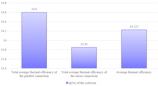
In order to obtain the total thermal efficiency of the two connections, the data from the series and parallel connections were analyzed, as shown in
Figure 24.
Figure 24. Average thermal efficiency of series and parallel connections.
Despite the low thermal efficiency at low ambient temperatures and considering the above conditions, with the solar collectors under study it was possible to achieve, at the end of each day, average water outlet temperatures from the solar collectors above the average of 36°C, which is ideal for bathing
| [15] | REIS, E. P. Análise do desempenho térmico de um sistema de aquecimento solar utilizando coletor com superfície absorvedora em chapas de forro de PVC. 2009. 85 f. Dissertação (Mestrado em Engenharia Mecânica) - Programa de Pós-Graduação em Engenharia Mecânica, Universidade Federal do Rio Grande do Norte, Natal-RN, 2009. |
[15]
. Thus, the system shows that in just one day of operation it is capable of heating water for bathing with good efficiency.
During the study days, based on the data collected on the first day, when the thermal efficiency of each collector was analyzed, and the remaining days when the study focused on the thermal efficiency of the connections, it was found that the highest average outlet temperature of the collector was 60.1°C on 09/13/2021 and the lowest average temperature was 45.91°C on 09/13/2021, both during the parallel connection study.
The day with the lowest inlet temperature was the second day (September 11, 2021), with an average inlet temperature of 48.80°C and an outlet temperature of 26.50°C. However, this result may have been caused by the reservoir due to several factors, such as the low ambient temperature compared to the other days of the study. The data show that parallel connection has higher thermal efficiency on both low-temperature and high-temperature days compared to series connection.
According to
| [12] | MIRANDA, Marco António Cunha. Optimização de sistemas solares térmicos. Dissertação submetida para satisfação parcial dos requisitos do grau de mestre em engenharia civil — especialização em construções civis. Julho de 2008. |
[12]
, the thermal efficiency of the system in parallel connection at high or normal temperatures is higher than that of the series connection. This case proves that the parallel connection achieved higher temperatures and efficiencies than the series connection, even with low ambient temperatures compared to the temperatures at which the series studies were conducted.
A eficiência térmica média de 34.6% alcançada pelos coletores configurados em paralelo é superior à eficiência térmica média de 33,85% alcançada pelos coletores solares configurados em série. Vários fatores influenciam a eficiência térmica, tais como perda de potência, temperatura, inclinação, área, etc. As perdas de potência observadas durante o inquérito estatístico mostraram que a eficiência térmica da ligação em paralelo era superior porque tinha uma perda de potência menor, com um valor de 1,24 kW em comparação com 1,26 kW para a ligação em série.
5. Conclusion
In accordance with the objectives outlined, this chapter of the study presents the conclusions:
For the study of solar collectors connected in series and in parallel, it was possible to gain a basic understanding of solar collectors, connections, and the behavior of construction materials. It was possible to build thermal systems capable of absorbing solar radiation for water heating, as these thermal systems depend exclusively on solar radiation, i.e., the more solar radiation that falls on the solar collector, the higher the temperature of the heated water, thus producing good thermal efficiency.
With the solar water heating system, such as the flat solar collectors developed, good temperature indices were obtained, between 37.7°C and 68.1°C, with a thermal efficiency of 52.9%. Meanwhile, conventional solar collectors sold on the domestic market and some installed on hospital roofs typically have a thermal efficiency of over 55%.
Power losses influenced many in obtaining the thermal efficiency of the two connections. The parallel connection showed greater thermal efficiency than the series connection in relation to power losses, as the parallel connection showed lower power loss, with a value of 1.24 kW compared to 1.26 kW for the series connection. The greater the power loss, the lower the thermal efficiency.
The low or varying temperature levels measured at the collector outlet may have been caused by heat loss due to the process of opening and closing the thermal reservoir cover every hour so that measurements could be taken, causing disruption to the circulation of water inside the reservoir or even shading at the time of measurement, without taking into account the variation in overall solar intensity at each hour of the day.
6. Recommendations
When assembling the water circulation grid, take great care when tightening the pipes to avoid creating water leaks. Ensure that the water circulation grid has no leaks before fixing and gluing the glass.
It is necessary to install a sufficient number of solar collectors to capture the necessary energy and choose the correct inclination to achieve good performance according to the capacity of the collectors.
Abbreviations
A | Collector |
cm | Centimeter |
Cp | Specific Heat |
EG | Global Solar Radiation Energy |
Edif | Diffuse Radiation Energy |
EG | Direct Radiation Energy |
I | Global Solar Radiation |
INAM | National Institute of Meteorology |
ṁ | Mass Flow Rate |
Pabs | Absolute Power |
Pp | Power Loss |
Pu | Useful Power |
Ta | Ambient Temperature |
Tec | Collector Inlet Temperature |
TF | Average Fluid Temperature |
Tsc | Collector Outlet Temperature |
m | Meter |
ΔT | Temperature Variation |
ηt | Thermal Efficiency |
J | Joul |
αp | Plate Absorptivity |
kW | Kilowatt |
°C | Graucelsius |
K | Kelvin |
W | Watt |
kg | Kilogram |
s | Seconds |
Conflicts of Interest
The author declares no conflicts of interest.
References
| [1] |
CEEN. Conexiones en Paralelo, Serie y Mixto. Certificacionenergetica. Julio 18, 2015
http//:certificacionenergetica.info/conexiones-en-paralelo-serie-y-mixto/
|
| [2] |
CERVEIRA, Manuel. Sistemas Térmicos de Energia Solar. Departamento de Engenharia Eletrotécnica. Trabalho de Projecto apresentado para a obtenção do grau de Mestre em Automação e Comunicações em Sistemas de Energia. Coimbra, Dezembro 2012.
|
| [3] |
BEZERRA, A. M. Aplicações térmicas da energia solar. 4. ed. João Pessoa: Universitária, 2001, Cap. 2, p. 47-96.
|
| [4] |
DUFFIE, John A.; BECKMAN, William A. Solar Engineering of Thermal Processes. New York: John Wiley& Sons, 1991.
|
| [5] |
FROTA, A. B; SCHIFFER, S. T. R. Manual de conforto térmico. 5. ed. São Paulo, Studio Nobel, 2001, 243p. ISBN 85-85445-39-4.
|
| [6] |
GUERRA; VARELLA. Análise do desempenho térmico de um sistema de aquecimento solar de baixo custo na cidade de Mossoró – RN. 2014. 98 f. Monografia - Graduação em Engenharia de Energia, Universidade Federal Rural do Semi-Árido, Mossoró-RN, 2012.
|
| [7] |
KISOLTEC. Aquecedor solar. Manual de instalação do aquecedor solar. Brazil. 2017.
|
| [8] |
LEBENA, Eduardo Pérez; COSTA, Jorge Cruz. Conversão térmica da energia solar. Portugal.
|
| [9] |
LOPO, Alexandre Boleira. Análise do desempenho térmico de um sistema de Aquecimento solar de baixo custo. Natal-RN, 2010.
|
| [10] |
Manual sobre tecnologias, projecto e instalação. Solar térmico. Janeiro de 2004
https://www.jgduarte.com/download/greenpro_fotovoltaico.pdf
|
| [11] |
MENDES, Bárbara de Morais. Estudo da influência de parâmetros de projeto no desempenho de coletoressolares planos. Departamento de engenharia de controle e automação e técnicas fundamentais. Universidade federal de ouro preto – ufop escola de minas. Ouro preto - mg 2017.
|
| [12] |
MIRANDA, Marco António Cunha. Optimização de sistemas solares térmicos. Dissertação submetida para satisfação parcial dos requisitos do grau de mestre em engenharia civil — especialização em construções civis. Julho de 2008.
|
| [13] |
NOVAIS; Marisa Sofia Teixeira. Energias Renováveis e Eficiência Energética. Escola Superior de Tecnologia e Gestão Instituto Politécnico de Bragança, Junho de 2014.
|
| [14] |
PEREIRA, Filipe e OLIVEIRA, Manuel; Curso Técnico Instalador de Energia Solar Fotovoltaico, 2011.
|
| [15] |
REIS, E. P. Análise do desempenho térmico de um sistema de aquecimento solar utilizando coletor com superfície absorvedora em chapas de forro de PVC. 2009. 85 f. Dissertação (Mestrado em Engenharia Mecânica) - Programa de Pós-Graduação em Engenharia Mecânica, Universidade Federal do Rio Grande do Norte, Natal-RN, 2009.
|
| [16] |
COELHO, Daniel Moreira. Identificação de variáveis críticas e simulação do uso de coletoressolares em prédios residenciais. Rio de Janeiro: Universidade Federal do Rio de Janeiro, 2011.
|
Cite This Article
-
APA Style
Chirape, S. M. (2025). Comparative Study of Flat Solar Collectors Connected in Series and in Parallel Using Readily Available Materials (in the City of Chimoio). Journal of Energy and Natural Resources, 14(3), 101-117. https://doi.org/10.11648/j.jenr.20251403.13
 Copy
|
Copy
|
 Download
ACS Style
Chirape, S. M. Comparative Study of Flat Solar Collectors Connected in Series and in Parallel Using Readily Available Materials (in the City of Chimoio). J. Energy Nat. Resour. 2025, 14(3), 101-117. doi: 10.11648/j.jenr.20251403.13
Copy
|
Download
AMA Style
Chirape SM. Comparative Study of Flat Solar Collectors Connected in Series and in Parallel Using Readily Available Materials (in the City of Chimoio). J Energy Nat Resour. 2025;14(3):101-117. doi: 10.11648/j.jenr.20251403.13
Copy
|
Download
-
@article{10.11648/j.jenr.20251403.13,
  author = {Simba Mequias Chirape},
  title = {Comparative Study of Flat Solar Collectors Connected in Series and in Parallel Using Readily Available Materials (in the City of Chimoio)
},
  journal = {Journal of Energy and Natural Resources},
  volume = {14},
  number = {3},
  pages = {101-117},
  doi = {10.11648/j.jenr.20251403.13},
  url = {https://doi.org/10.11648/j.jenr.20251403.13},
  eprint = {https://article.sciencepublishinggroup.com/pdf/10.11648.j.jenr.20251403.13},
  abstract = {The article approaches in a comparative way the series and parallel connection of flat solar collectors using glass covers, creating a low-cost, easy-to-assemble solar thermal system in the Heróis Mozambicanos neighborhood, in the city of Chimoio. The thermal efficiency of each collector and each connection made in the solar collectors was analyzed. These solar collectors have good outlet temperatures, as they can heat water to the recommended ideal temperature, which is above 30°C. Therefore, this article approaches the use of solar energy using low-cost systems that are accessible to the population, built with materials that are easily found in the national market, for basic purposes. To carry out this article, the experimental method was used, which consisted of producing two prototypes of solar collectors. In addition to the experimental method, a bibliographic analysis technique was used, which consisted of gathering information in books, dissertations, websites, and manuals already published on the subject. For data collection, opted to use a TPM-10 digital thermometer, which consisted of viewing temperature data, and a cell phone stopwatch to measure the time spent during the time intervals under study. Microsoft Office Excel was used for data analysis, and temperature data obtained on instruments during the study was used to determine thermal efficiency, yield, useful power, and global solar radiation. With the solar water heating system, such as the flat solar collectors developed, good temperature indices were obtained, between 37.7°C and 68.1°C, with a thermal efficiency of 52.9%. Meanwhile, conventional solar collectors sold on the domestic market and some installed on hospital roofs typically have a thermal efficiency of over 55%.
},
 year = {2025}
}
Copy
|
Download
-
TY  - JOUR
T1  - Comparative Study of Flat Solar Collectors Connected in Series and in Parallel Using Readily Available Materials (in the City of Chimoio)

AU  - Simba Mequias Chirape
Y1  - 2025/09/26
PY  - 2025
N1  - https://doi.org/10.11648/j.jenr.20251403.13
DO  - 10.11648/j.jenr.20251403.13
T2  - Journal of Energy and Natural Resources
JF  - Journal of Energy and Natural Resources
JO  - Journal of Energy and Natural Resources
SP  - 101
EP  - 117
PB  - Science Publishing Group
SN  - 2330-7404
UR  - https://doi.org/10.11648/j.jenr.20251403.13
AB  - The article approaches in a comparative way the series and parallel connection of flat solar collectors using glass covers, creating a low-cost, easy-to-assemble solar thermal system in the Heróis Mozambicanos neighborhood, in the city of Chimoio. The thermal efficiency of each collector and each connection made in the solar collectors was analyzed. These solar collectors have good outlet temperatures, as they can heat water to the recommended ideal temperature, which is above 30°C. Therefore, this article approaches the use of solar energy using low-cost systems that are accessible to the population, built with materials that are easily found in the national market, for basic purposes. To carry out this article, the experimental method was used, which consisted of producing two prototypes of solar collectors. In addition to the experimental method, a bibliographic analysis technique was used, which consisted of gathering information in books, dissertations, websites, and manuals already published on the subject. For data collection, opted to use a TPM-10 digital thermometer, which consisted of viewing temperature data, and a cell phone stopwatch to measure the time spent during the time intervals under study. Microsoft Office Excel was used for data analysis, and temperature data obtained on instruments during the study was used to determine thermal efficiency, yield, useful power, and global solar radiation. With the solar water heating system, such as the flat solar collectors developed, good temperature indices were obtained, between 37.7°C and 68.1°C, with a thermal efficiency of 52.9%. Meanwhile, conventional solar collectors sold on the domestic market and some installed on hospital roofs typically have a thermal efficiency of over 55%.

VL  - 14
IS  - 3
ER  -
Copy
|
Download