Research Article | | Peer-Reviewed

Hydrodynamic Performance Enhancement of a Lift-type Vertical-axis In-pipe Water Turbine Using a Flow Deflector: A CFD-based Parametric Study

Received: 16 January 2026     Accepted: 27 January 2026     Published: 11 February 2026
Views:       Downloads:
Abstract

The use of existing water distribution infrastructure for micro-hydropower generation offers a practical pathway toward decentralized and low-carbon energy production. Lift-type vertical-axis water turbines (VAWTs) are particularly attractive for in-pipe applications because they operate independently of flow direction and can achieve relatively high efficiency at moderate rotational speeds. However, their performance is often constrained by unsteady flow behavior, torque fluctuations, and associated pressure losses in confined pipeline environments. This study numerically investigates the effectiveness of a stationary flow deflector in enhancing the hydrodynamic performance of a lift-type vertical-axis in-pipe water turbine. Three-dimensional unsteady computational fluid dynamics (CFD) simulations were conducted to evaluate turbine operation with and without a deflector under gravity-fed pipeline conditions. The effects of blade number and tip-speed ratio were systematically examined. Key performance indicators, including instantaneous and time-averaged torque, power output, pressure drop, and hydraulic efficiency, were quantified and compared. The results show that the introduction of the flow deflector significantly improves flow guidance toward the windward blades, leading to stronger lift generation and reduced flow separation. Across the investigated operating range, the deflector-assisted turbine achieved torque increases of approximately 20-30% and power output improvements of up to 30-40% relative to the baseline configuration without a deflector. Peak hydraulic efficiency was observed at moderate tip-speed ratios, with efficiency gains of approximately 15-25%. At the same time, the additional pressure loss introduced by the deflector remained limited, typically below 5% of the equivalent pressure head. Furthermore, torque fluctuations were noticeably reduced, indicating more stable turbine operation. These findings demonstrate that flow deflectors can effectively mitigate the unsteady hydrodynamic limitations of lift-type in-pipe turbines while preserving acceptable pressure losses, providing new design insights for micro-hydropower energy recovery in water distribution networks.

Published in Science Journal of Energy Engineering (Volume 14, Issue 1)
DOI 10.11648/j.sjee.20261401.12
Page(s) 7-20
Creative Commons

This is an Open Access article, distributed under the terms of the Creative Commons Attribution 4.0 International License (http://creativecommons.org/licenses/by/4.0/), which permits unrestricted use, distribution and reproduction in any medium or format, provided the original work is properly cited.

Copyright

Copyright © The Author(s), 2026. Published by Science Publishing Group

Keywords

Lift-type Vertical-axis Water Turbine, In-pipe Hydropower, Flow Deflector, Computational Fluid Dynamics (CFD), Micro-hydropower

1. Introduction
The accelerating global demand for clean, reliable, and decentralized energy has intensified interest in renewable technologies that can be integrated into existing infrastructure. Among the available renewable options, hydropower remains one of the most mature, predictable, and energy-dense sources of electricity generation . While large-scale hydropower systems dominate global installed capacity, their environmental footprint, long development timelines, and geographic constraints have shifted attention toward small- and micro-scale hydropower solutions that can be deployed with minimal ecological disruption . In this context, energy recovery from existing water distribution systems particularly gravity-fed pipelines, has emerged as a promising and largely untapped opportunity.
Water distribution networks frequently operate under surplus hydraulic head, which is traditionally dissipated through pressure reducing valves to protect downstream infrastructure . Replacing or supplementing these valves with in-pipe turbines enables the conversion of otherwise wasted hydraulic energy into useful electricity without compromising water supply reliability . Such systems are especially attractive for powering remote sensors, monitoring equipment, and localized electrical loads, thereby supporting smart water networks and decentralized energy strategies . However, the confined geometry of pipelines imposes strict constraints on turbine design, requiring compact configurations that deliver meaningful power output while maintaining low pressure losses.
Vertical-axis water turbines (VAWTs) have gained increasing attention for in-pipe hydropower applications due to their compact footprint, mechanical simplicity, and independence from flow direction . Compared with horizontal-axis designs, lift-type VAWTs can achieve higher power coefficients under steady flow conditions and are better suited for operation at moderate to high tip-speed ratios . Nevertheless, their performance in confined pipeline environments is often hindered by unsteady hydrodynamic phenomena, including dynamic stall, flow separation, and strong torque fluctuations . These effects not only reduce power output but also lead to mechanical vibrations and operational instability, limiting the practical deployment of lift-type in-pipe turbines.
Flow control strategies have been widely investigated as a means of improving turbine performance by guiding incoming flow and enhancing energy extraction. In open-flow and pipeline environments, the use of flow deflectors or guide vanes has been shown to significantly improve the performance of drag-type turbines by redirecting flow toward the advancing blades and increasing local flow velocity . Numerical and experimental studies report notable gains in torque and power output for deflector-assisted drag-type turbines, albeit sometimes accompanied by increased pressure losses . Despite these advances, the application of deflectors to lift-type vertical-axis turbines particularly within confined pipeline flows remains comparatively underexplored.
Existing studies on lift-type in-pipe turbines have primarily focused on blade geometry optimization, rotor solidity, helicity, and operating tip-speed ratios . While these investigations provide valuable insights into turbine design, they do not fully address the inherent unsteady flow behavior that limits performance in confined environments. Moreover, the hydrodynamic interaction between a stationary flow deflector and a rotating lift-type VAWT has not been systematically quantified. Key performance indicators such as torque generation, power output, pressure drop, and hydraulic efficiency under deflector-assisted operation remain insufficiently understood, creating a critical knowledge gap that hinders design optimization and real-world deployment.
To address this gap, the present study conducts a comprehensive computational investigation of a lift-type vertical-axis in-pipe water turbine integrated with a flow deflector. Using three-dimensional unsteady computational fluid dynamics (CFD), the hydrodynamic performance of the turbine is analyzed under gravity-fed pipeline conditions. The effects of blade number and tip-speed ratio are systematically examined while maintaining a fixed deflector configuration, enabling a clear assessment of deflector-induced performance changes. Key metrics including instantaneous and time-averaged torque, power output, pressure loss, and hydraulic efficiency are evaluated and compared against a baseline turbine without a deflector.
The results demonstrate that the incorporation of a flow deflector significantly enhances flow guidance toward the windward blades, leading to higher torque generation, increased power output, and improved hydraulic efficiency, while maintaining acceptable pressure losses within the pipeline. Furthermore, the deflector reduces torque fluctuations, contributing to more stable turbine operation. These findings confirm the effectiveness of deflector-assisted flow control for lift-type in-pipe turbines and provide practical design insights for the development of efficient micro-hydropower systems in water distribution networks.
2. Literature Review
Energy recovery from water conveyance systems has attracted increasing research attention as a viable pathway for decentralized and low-impact renewable power generation. In-pipe hydropower turbines, particularly vertical-axis configurations, are well suited for such applications due to their compact geometry and compatibility with confined flows. Early comparative studies by Yang et al. demonstrated that both lift-type and drag-type vertical-axis pipeline turbines can achieve acceptable hydraulic performance, with lift-type turbines exhibiting higher power coefficients under similar tip-speed ratios, albeit with less stable startup behavior . Importantly, these studies highlighted the need to balance power extraction with pressure loss to avoid compromising water supply functionality.
Blade design and rotor configuration have been shown to play a dominant role in turbine performance. Numerical and experimental investigations on conventional hydraulic turbines, such as Kaplan turbines, confirmed that increasing blade number and optimizing chord distribution can significantly improve efficiency, particularly under low-flow conditions . Similar trends have been observed for vertical-axis devices, where increased blade solidity generally enhances torque and power output but may also increase hydraulic losses if not carefully optimized .
Considerable effort has been devoted to improving turbine performance through blade profile innovation and hybrid lift-drag concepts. Combined lift-drag (CLD) blade designs applied to Savonius turbines have demonstrated notable improvements in power coefficient compared to conventional drag-only configurations . These studies confirm that exploiting both lift and drag mechanisms can enhance energy extraction, especially at low tip-speed ratios. Reviews of Darrieus and lift-type turbine design approaches further emphasize the importance of airfoil selection, solidity, and unsteady flow modeling in achieving reliable performance predictions .
Recent advances in computational fluid dynamics (CFD) have enabled detailed investigation of in-pipe lift-type turbines under realistic operating conditions. Three-dimensional numerical studies of spherical and helical lift-based in-pipe turbines revealed strong dependencies of power output and efficiency on blade number, chord length, helicity, and pitch angle . These works also showed that pressure losses introduced by well-designed lift-type turbines can remain within acceptable limits, typically below 3% of the total pipeline head. However, they also reported that increased solidity has a more pronounced effect on head loss than other geometric parameters.
Beyond blade and rotor optimization, several studies have explored flow control strategies to improve turbine performance. Deflectors, guide plates, and flow-disturbing elements have been successfully applied to drag-type turbines and hybrid configurations to redirect incoming flow toward the advancing blades, resulting in substantial power gains . Experimental and numerical investigations reported power output increases of up to 80% in some cases when deflectors were optimally positioned . Similar benefits were observed in combined Darrieus-Savonius turbines, where deflectors improved torque generation and startup behavior .
In parallel with these developments, some recent studies have employed the volume of fluid method to investigate turbine performance in hydraulic systems involving free-surface or multiphase flow conditions. These studies primarily focus on scenarios where air-water interface dynamics, surface deformation, or partial conduit filling significantly influence turbine loading and efficiency. Volume of fluid-based simulations have been shown to effectively capture transient interface behavior, vortex evolution, and pressure fluctuations in hydrokinetic and conduit-based turbine applications operating under non-fully flooded conditions . Such investigations provide valuable insights into unsteady turbine-flow interactions when phase interfaces are present, although their applicability is mainly limited to free-surface or multiphase environments rather than fully pressurized pipelines.
Despite these advances, the majority of deflector-based studies have focused on drag-type or hybrid turbines, wind turbines, or open-flow hydrokinetic devices . Investigations involving lift-type vertical-axis turbines have largely concentrated on blade aerodynamics, solidity, and operating tip-speed ratios, with little attention given to deflector-assisted flow control in confined pipeline environments . Notably, no systematic CFD-based study has quantified the hydrodynamic impact of a stationary deflector on the performance of a lift-type vertical-axis in-pipe water turbine.
Therefore, a clear knowledge gap exists regarding the use of flow deflectors to enhance the performance of lift-type vertical-axis turbines in pipeline applications. Addressing this gap is essential for mitigating unsteady flow effects, improving torque stability, and increasing power output while maintaining acceptable pressure losses. The present study directly responds to this gap by numerically investigating a deflector-assisted lift-type vertical-axis in-pipe water turbine, providing new quantitative insights into its hydrodynamic performance and practical applicability.
3. Methodology
3.1. Geometric Modeling
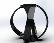
Figure 1. 3D modeled Gorlov pipe turbine geometry.
A three-dimensional model of a lift-type vertical-axis water turbine was developed for integration into a circular gravity-fed pipeline. The turbine geometry consists of a centrally mounted vertical shaft supporting multiple lift-based blades arranged symmetrically around the rotor circumference. The blade profile and geometric parameters were selected based on established lift-type turbine design principles to ensure adequate flow interaction while maintaining sufficient flow permeability within the pipe. Schematic of the turbine geometry and blade profile is presented in Figures 1 and 2, respectively, while the principal geometric parameters are summarized in Table 1.
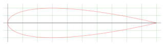
Figure 2. Hydrofoil NACA 0020 blade profile of the VAWT.
Table 1. Geometric parameters of the lift-type VAWT and computational domain.

Parameter

Value/Range

Pipe inner diameter (Dp)

200 mm

Total pipeline length (Lp)

3800 mm

Upstream pipe length (Lu)

1400 mm

Downstream pipe length (Ld)

2400 mm

Turbine rotor diameter (Dr)

0.85 Dp

Turbine height (H)

= Dp

Number of blades (N)

3, 4, 5

Blade chord length (c)

0.15 Dr

Blade profile

Lift-type hydrofoil/thin plate arc

Turbine solidity (σ)

0.2, 0.3, 0.4

Solidity range

0.2-0.6

Deflector shrinkage ratio (ε)

0.58

A stationary flow deflector was positioned upstream of the turbine to redirect the incoming flow toward the windward blades. The deflector geometry was designed to partially block the pipe cross-section, thereby accelerating the flow locally while minimizing excessive hydraulic losses. The relative position of the deflector with respect to the turbine rotor and the resulting contraction of the flow passage are illustrated in Figure 3. The deflector shrinkage ratio, defined as the ratio of the blocked area to the pipe cross-sectional area, was maintained constant throughout the simulations in order to isolate the effects of blade number and rotational speed on turbine performance. Previous studies were carried out with a blockage ratio ranging from 0.58-0.9, and it was discovered that a blockage level of 80% provides a better efficiency. In this numerical analysis, a deflector was placed such that the blockage ratio was 0.8. The angle of deflector considered for the simulation was 15° and 20° respectively.
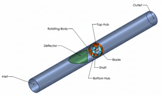
Figure 3. Computational domain.
3.2. Computational Domain and Boundary Conditions
The computational domain consists of three main regions: an upstream pipe section to ensure fully developed inflow conditions, a central turbine-deflector interaction region, and a downstream pipe section to allow pressure recovery and wake dissipation. The overall domain layout and dimensions are shown in Figure 3. The upstream and downstream lengths were selected in accordance with best practices for confined-flow turbine simulations to minimize boundary-induced numerical artifacts.
At the inlet, a uniform velocity boundary condition was imposed to represent steady gravity-driven flow within the pipeline. The outlet boundary was defined using a static pressure condition corresponding to atmospheric reference pressure. All pipe walls, turbine blades, shaft, and deflector surfaces were treated as no-slip walls. These boundary conditions are summarized in Table 2.
Table 2. Boundary Conditions and Operating Parameter.

Boundary / Parameter

Specification

Description

Inlet boundary condition

Velocity inlet

Uniform inlet velocity

Inlet flow direction

Axial

Aligned with pipe centerline

Outlet boundary condition

Pressure outlet

0 Pa (gauge pressure)

Pipe wall

No-slip wall

Stationary

Turbine blades

No-slip wall

Rotating

Turbine shaft

No-slip wall

Rotating

Deflector surface

No-slip wall

Stationary

Fluid type

Water

Incompressible

Fluid density

ρ

998 kg.m-3

Dynamic viscosity

μ

0.001 Pa.s

Turbulence model

URANS, k-ε

Standard wall functions

Reference pressure

-

Atmospheric

Operating temperature

-

Constant

Gravity

-

Neglected

3.3. Governing Equations
The flow was modeled as incompressible and turbulent. The unsteady Reynolds-Averaged Navier-Stokes (URANS) equations were solved to capture the time-dependent interaction between the rotating turbine blades and the surrounding flow. The continuity and momentum equations governing the flow are expressed as Eq. (1) and Eq. (2), respectively:
u=0(1)
ut+(u)u=-1ρp+ν2u+Ft(2)
where u is the velocity vector, p is pressure, ρ is fluid density, νis kinematic viscosity, and Ft represents the turbulence-induced Reynolds stresses.
3.4. Turbulence Modeling
Turbulence effects were modeled using the standard k-ε model, which is widely adopted for internal turbulent flows involving flow separation and rotating machinery due to its numerical robustness and reasonable computational cost. This model has been successfully applied in previous numerical investigations of in-pipe turbines and vertical-axis flow devices under confined conditions .
The transport equation for the turbulent kinetic energy k is given by:
(ρk)t+(ρkuj)xj=xjμμtσkkxj+Gk-ρε(3)
The transport equation for the turbulence dissipation rate εis expressed as:
(ρε)t+(ρεuj)xj=xjμμtσεεxj+C1εεkGk-C2ερε2k(4)
where
k is the turbulent kinetic energy,
ε is the rate of dissipation of turbulent kinetic energy,
ρ is the fluid density,
uj represents the velocity components,
μ is the molecular viscosity,
μt is the turbulent (eddy) viscosity,
Gk is the production of turbulent kinetic energy due to mean velocity gradients,
σk and σε are the turbulent Prandtl numbers for k and ε, respectively.
The turbulent viscosity μt is computed using:
μt=ρCμk2ε(5)
The model constants were taken as:
Cμ=0.09,C1ε=1.44,C2ε=1.92,σk=1.0,σε=1.3
Standard wall functions were employed near solid boundaries to model near-wall turbulence behavior, ensuring numerical stability while maintaining reasonable computational cost. The adequacy of the turbulence model was verified by achieving periodic convergence of torque and pressure signals over successive turbine revolutions.
3.5. Mesh Generation and Grid Independence
The computational domain was discretized using an unstructured finite-volume mesh. Local mesh refinement was applied in regions of high velocity gradients, particularly near the turbine blades, shaft, deflector surfaces, and wake region. A representative mesh distribution is shown in Figure 4, highlighting the near-wall refinement and rotating domain interface.
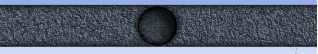
Figure 4. Generated mesh.
To ensure numerical accuracy, a grid independence study was performed using three progressively refined meshes . The effect of mesh resolution on time-averaged torque and pressure drop was evaluated, and mesh convergence was achieved when variations in key performance metrics remained below 2%. The final mesh statistics and grid sensitivity results are provided in Table 3.
Table 3. Mesh statistics and grid independence study.

Mesh Level

Total Cell Count

Minimum Cell Size

Max Skewness

Avg. Torque Deviation

Coarse mesh

0.9 × 10⁶

Larger

< 0.85

Reference

Medium mesh

1.6 × 10⁶

Moderate

< 0.80

< 4%

Fine mesh

2.4 × 10⁶

Refined near blades

< 0.75

< 2%

Final mesh selected

2.4 × 10⁶

Refined

< 0.75

< 2%

Note: Local mesh refinement was applied near turbine blades, shaft, deflector surfaces, and wake regions. Grid independence was achieved when further mesh refinement resulted in less than 2% variation in time-averaged torque and pressure drop.
3.6. Performance Evaluation
Turbine performance was evaluated using non-dimensional and dimensional metrics commonly adopted in vertical-axis turbine analysis . The instantaneous torque acting on the turbine shaft was obtained by integrating pressure and viscous forces on the blade surfaces. Time-averaged torque Twas computed over a complete rotor revolution.
The hydraulic power available in the pipeline upstream of the turbine is calculated as:
Phyd=ρgQH(6)
where
Phyd is the available hydraulic power (W),
ρ is the density of water (kg·m-3),
g is the gravitational acceleration (m·s-2),
Q is the volumetric flow rate (m3·s-1), and
H is the available hydraulic head across the turbine location (m).
The hydraulic head H is related to the pressure difference across the turbine-deflector system by:
H=Δpρg(7)
where Δpis the pressure drop across the turbine (Pa).
The hydraulic head considered in this study represents an equivalent pressure head derived from the pressure drop (Δp) across the turbine-deflector system, rather than an elevation-induced gravitational head.
The mechanical power extracted by the turbine is determined from the time-averaged torque and angular velocity as:
Pmech=Tω(8)
where
Tis the time-averaged torque acting on the turbine shaft (N·m), and
ω is the angular velocity of the turbine (rad·s-1).
Finally, the hydraulic efficiency of the turbine is defined as the ratio of extracted mechanical power to the available hydraulic power:
ηh=PmechPhyd=TωρgQH(9)
The tip-speed ratio, defined in Eq. (10), was used as the primary operating parameter to compare turbine performance across different rotational speeds and blade numbers.
λ=ωRU(10)
where
λ is the tip-speed ratio (-),
ω is the angular velocity of the turbine (rad·s-1),
R is the turbine rotor radius (m), and
U is the inlet flow velocity of the water (m·s-1).
3.7. Parametric Study
A parametric study was conducted by varying the number of turbine blades and the rotational speed while maintaining constant inlet flow conditions and deflector geometry. The complete set of simulation cases is summarized in Table 4. This approach enabled systematic evaluation of the combined effects of rotor solidity and tip-speed ratio on turbine performance .
Table 4. Simulation matrix for baseline and deflector-assisted turbine configurations.

Case ID

Configuration

Number of blades, N

Solidity, σ

Tip-speed ratio, λ

Deflector

B1

Baseline

3

0.2

1

No

B2

Baseline

3

0.2

1.5

No

B3

Baseline

3

0.2

2

No

B4

Baseline

4

0.3

1

No

B5

Baseline

4

0.3

1.5

No

B6

Baseline

4

0.3

2

No

B7

Baseline

5

0.4

1

No

B8

Baseline

5

0.4

1.5

No

B9

Baseline

5

0.4

2

No

D1

Deflector-assisted

3

0.2

1

Yes

D2

Deflector-assisted

3

0.2

1.5

Yes

D3

Deflector-assisted

3

0.2

2

Yes

D4

Deflector-assisted

4

0.3

1

Yes

D5

Deflector-assisted

4

0.3

1.5

Yes

D6

Deflector-assisted

4

0.3

2

Yes

D7

Deflector-assisted

5

0.4

1

Yes

D8

Deflector-assisted

5

0.4

1.5

Yes

D9

Deflector-assisted

5

0.4

2

Yes

Note: All simulations were conducted using identical pipe geometry, inlet flow conditions, and numerical settings. For deflector-assisted cases (D1-D9), the deflector geometry, position, and shrinkage ratio (ε=0.58) were kept constant. The baseline cases (B1-B9) serve as direct reference configurations for isolating the hydrodynamic effects of the flow deflector.
4. Results and Discussion
4.1. Model Validation
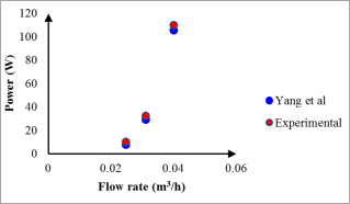
Figure 5. Comparison of predicted and reference power flowrate.
Model validation is a critical step in demonstrating the credibility of CFD predictions for rotating turbines in confined flows. The present numerical framework was validated against published experimental/numerical performance data for a vertical-axis in-pipe lift-type turbine reported by Yang et al. (2019) . The comparison of predicted and reference power over a range of flow rate values is shown in Figure 5.
Overall, the model reproduces the performance trend reported in the reference study and yields an average deviation of approximately 4% for the power (Figure 5). This is within the commonly accepted range for URANS-based turbine simulations and supports the suitability of the present ANSYS Fluent approach with a k-ε turbulence closure for comparative parametric analysis of in-pipe turbine configurations . The validation outcome shows that the numerical setup captures the dominant physics governing lift-type turbine performance in confined pipeline flow, enabling meaningful comparisons across blade number and deflector arrangements.
4.2. Effect of Blade Number and Turbine Solidity
The blade number Nstrongly influences turbine solidity and therefore the balance between lift production and blockage-induced hydraulic losses. In this study, three, four, and five blades were investigated to quantify the sensitivity of performance to solidity under confined conditions. Practical design considerations also motivate this range: in-pipe lift-based devices (including spherical/helical concepts) are often constrained by hub/assembly geometry and flow passage limitations, which can restrict feasible blade counts and chord choices .
The turbine solidity was calculated using:
σ=NcπDr(11)
where c is the blade chord and Dris the turbine rotor diameter. Increasing Nincreases σ, enhancing the rotor’s effective interaction with the flow and potentially increasing torque and power, but also increasing hydraulic resistance and the likelihood of strong wake interaction between blades.
These competing effects are well established for vertical-axis turbines: higher solidity can improve starting and torque capacity, but excessive solidity tends to penalize performance by increasing losses and reducing effective inflow through the rotor . In confined pipelines, these tradeoffs can be amplified because blockage and pressure recovery are limited by the conduit geometry .
4.3. Power and Hydraulic Efficiency Trends
4.3.1. Blade Number Influence at Optimal Operating Conditions
Figures 6 and 7 present the turbine power and hydraulic efficiency as functions of RANS Tip-Speed Ratio (TSR) for different blade numbers. A clear optimum is observed, with performance increasing with TSR up to a peak before declining, consistent with lift-type turbine behavior where excessive TSR can lead to unfavorable angles of attack and increased viscous and wake losses .
At the optimal operating region, the four-blade configuration had the highest reported performance in this study, producing approximately 640 W and a peak hydraulic efficiency of 65%. In comparison, the three-blade and five-blade cases produced approximately 430 W and 360 W, with efficiencies of about 61% and 57%, respectively (Figures 6, 7).
The decline observed for the five-blade case despite its higher solidity suggests that the added blades increase internal flow resistance and blade-to-blade wake interaction, which can intensify unsteady loading and reduce net power extraction. This trend aligns with the broader understanding that increasing blade count can improve torque capacity, but beyond an optimum the additional blades can increase losses and reduce efficiency, particularly in constrained passages .
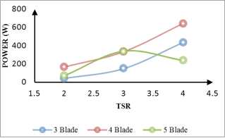
Figure 6. Power (W) vs TSR for different blade numbers.
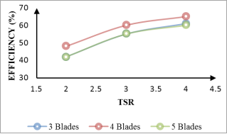
Figure 7. Efficiency (%) vs TSR for different blade numbers.
4.3.2. Deflector Angle Influence
Flow deflectors are widely used in drag-type and hybrid devices to redirect flow toward the advancing blade region and improve effective inflow conditions . In the present lift-type in-pipe configuration, changing the deflector angle significantly affected turbine power output. When the deflector angle was adjusted from 20° to 15°, the maximum power decreased from approximately 641 W to 414 W (Figure 8).
This result indicates that the deflector angle controls the degree of flow redirection and local acceleration into the windward sector. A larger deflector angle (within the tested range) likely produced stronger guidance/acceleration, improving blade incidence conditions and lift generation. Similar sensitivity to deflector geometry/position has been reported for pipeline turbines, where optimal deflector settings maximize useful flow deflection while limiting pressure losses .
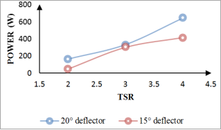
Figure 8. Power (W) vs TSR for different deflector angles.
4.4. Torque and Blade Force Characteristics
Torque production in lift-type VAWTs is inherently unsteady due to the periodic variation in relative velocity and angle of attack with azimuthal position. To quantify blade-level loading, the tangential driving force FT was obtained from the resolved blade forces in the global coordinate system:
FT=FXcosθ-FYsinθ(12)
where FX and FY are the resolved force components on the blade and θis the azimuthal angle.
The torque contribution was computed from the tangential force (via the blade moment arm), and the half-revolution histories of driving force and torque are presented in Figure 9. The results show that both tangential force and torque rise with rotation and reach a maximum around 50° azimuth, after which they decline as the blade approaches the downstream sector. The observed reduction toward 180° is consistent with increased likelihood of flow separation/dynamic stall and wake interference, which reduce effective lift and therefore driving torque .
The role of the deflector can be interpreted in this framework: by increasing the inflow velocity and improving local incidence conditions in the windward sector, the deflector can increase peak driving force and improve the cycle-averaged torque, thereby increasing power output. This is consistent with the performance enhancements reported in deflector-assisted confined-flow turbine studies .
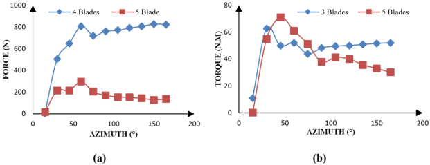
Figure 9. Turbine driving force and output torque over half revolution: (a) tangential driving force; (b) torque.
4.5. Flow Field Analysis (Velocity and Pressure Distributions)
To connect the performance trends to physical mechanisms, the mid-plane velocity and pressure contours are presented in Figure 10 for three- and four-blade configurations at representative TSR values. The contours show that increasing blade number generally increases flow resistance within the rotating domain, which tends to reduce local velocity in the rotor zone and increase static pressure upstream of/within the rotor region. In lift-type turbines, a controlled increase in pressure difference and appropriate flow incidence can enhance lift, but excessive deceleration and blockage can reduce energy extraction and increase losses.
The four-blade configuration shows a more favorable balance: sufficient rotor-flow interaction to generate lift and torque, while maintaining better internal flow passage than the five-blade case. These qualitative flow field observations are consistent with reported confined-conduit lift-type turbine studies, where blade number/chord modifications alter both power and pressure-drop characteristics .
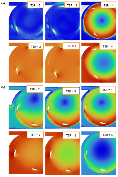
Figure 10. Mid-section flow fields showing pressure (Pa) and velocity magnitude (m/s) at different TSR values: (a) three-blade turbine; (b) four-blade turbine.
4.6. Comparison with Relevant Literature
The observed performance characteristics are consistent with major findings in the pipeline turbine literature. Yang et al. reported that lift-type vertical-axis pipeline turbines can achieve higher power coefficients than drag-type designs under comparable TSR, though stability and unsteady behavior require careful consideration . Similarly, Diab et al. showed that blade number and chord selection substantially affect both power and pressure loss, with diminishing returns beyond an optimal chord/solidity range due to increased losses . The sensitivity of turbine output to flow-guiding elements (deflectors) also aligns with earlier reports on deflector-assisted turbines, where improved inflow guidance leads to measurable gains in power, but the outcome depends strongly on the deflector geometry, angle, and placement .
4.7. Implications and Future Work
The results indicate that, for the investigated in-pipe lift-type turbine, four blades provide the best balance between lift generation and confined-flow losses, while the deflector angle significantly affects achievable power output. These findings suggest that practical in-pipe deployment should focus on optimizing the combined turbine-deflector configuration to maximize power while maintaining acceptable pressure drop.
It is important to clarify the choice of numerical modeling approach adopted in the present study in relation to recent investigations that employ the volume of fluid method . The volume of fluid framework is particularly suited for hydraulic systems involving free-surface effects, air-water interface dynamics, or multiphase interactions, where surface deformation, phase fraction transport, and interface-induced unsteadiness play a dominant role in governing turbine performance. Consequently, volume of fluid-based simulations have been successfully applied in studies addressing open-channel flows, partially filled conduits, wave-structure interaction, and other multiphase configurations .
Future work should include:
1) Experimental validation of the deflector-assisted lift-type configuration under controlled pipeline conditions.
2) Deflector geometry optimization (angle, curvature, shrinkage ratio, and distance to rotor), building on existing confined-flow deflector studies .
3) Quantification of pressure drop/head loss in parallel with power output to establish the best energy-recovery trade-off in real water distribution systems .
4) Investigation of advanced turbulence models (e.g., SST k-ω, DES) for improved resolution of dynamic stall and wake interaction under high TSR operation .
5) Extension to volume of fluid-based modeling for cases involving free-surface or multiphase flow conditions (e.g., partial pipe filling, air entrainment, and transient start-up or shutdown events), where air-water interface dynamics may become relevant to turbine performance .
5. Conclusions
This study numerically investigated the hydrodynamic performance of a deflector-assisted lift-type vertical-axis in-pipe water turbine using unsteady CFD simulations. The effects of blade number (solidity), tip-speed ratio, and deflector configuration on turbine power output, hydraulic efficiency, torque characteristics, and internal flow structure were systematically examined under confined pipeline conditions.
The numerical model was first validated against published reference data for a lift-type vertical-axis pipeline turbine, showing good agreement with an average deviation of approximately 4% in predicted power. This validation confirms the suitability of the URANS-based ANSYS Fluent framework with a k-ε turbulence model for comparative performance analysis of in-pipe lift-type turbines.
A key finding of the study is the identification of an optimal blade number for the investigated configuration. Increasing the blade number from three to four significantly enhanced turbine performance due to increased rotor-flow interaction and improved lift generation. The four-blade turbine achieved the highest power output (640 W) and hydraulic efficiency (65%) at its optimal tip-speed ratio. However, further increasing the blade number to five resulted in reduced performance, despite higher solidity, due to intensified flow blockage, blade-wake interaction, and unsteady torque fluctuations. This highlights the existence of a clear solidity-dependent performance optimum for lift-type turbines operating in confined pipelines.
The introduction of a stationary flow deflector was shown to have a substantial impact on turbine performance. Deflector geometry and angle strongly influenced the effective inflow conditions at the rotor. A larger deflector angle within the investigated range enhanced local flow acceleration and improved blade incidence, leading to significantly higher power output compared with smaller deflector angles. These findings demonstrate that deflectors previously applied predominantly to drag-type or hybrid turbines can also be effectively employed to enhance the performance of lift-type vertical-axis in-pipe turbines, addressing a notable gap in existing research.
Flow field analyses revealed that performance improvements are directly linked to changes in internal velocity and pressure distributions within the rotating domain. The optimal configuration achieved a favorable balance between lift augmentation and hydraulic losses, while excessive blade solidity or sub-optimal deflector settings led to flow deceleration, increased pressure buildup, and reduced net energy extraction. Blade-resolved force and torque analyses further showed that peak torque occurs in the windward area of rotation, with performance deterioration in the downstream region due to flow separation effects that can be partially mitigated through appropriate flow redirection by the deflector.
Abbreviations

CFD

Computational Fluid Dynamics

VAWT

Vertical-Axis Water Turbine

URANS

Unsteady Reynolds-Averaged Naiver-Stokes

TSR

Tip-Speed Ratio

VOF

Volume of Fluid

PRV

Pressure Reducing Valve

RANS

Reynolds-Averaged Naiver-Stokes

Acknowledgments
Special thanks to the Applied Energy and Fluid Machinery Lab of the Department of Mechanical Engineering, University of Cross River State, Nigeria for providing the necessary research tools.
Author Contributions
Samuel Effiom: Conceptualization, Investigation, Writing – original draft, Supervision, Project Administration.
Maria Kaka Enoh: Supervision, Validation, Writing – review & editing, Data Curation.
Omini Jimmy: Conceptualization, Methodology, Writing – original draft, Formal Analysis.
Precious-Chibuzo Effiom: Methodology, Formal Analysis, Visualization, Writing – review & editing.
Nkpa Ogarekpe: Methodology, Writing – review & editing, Project Administration, Resources.
Conflicts of Interest
The authors declare no conflicts of interest.
References
[1] Singh, V. K., Singal, S. K. Operation of hydro power plants - A review. Renewable and Sustainable Energy Reviews. 2017, 69, 610-619.
[2] Anaza, S. O., Abdulazeez, M. S., Yisah, Y. A., Yusuf, Y. O., Salawu, B. U., Momoh, S. U. Micro hydro-electric energy generation - An overview. American Journal of Engineering Research (AJER). 2017, 6(2), 5-12.
[3] Yuksel, I., Kaygusuz, K. Renewable energy sources for clean and sustainable energy policies in Turkey. Renewable and Sustainable Energy Reviews. 2011, 15(8), 4132-4144.
[4] Voltz, T. J., Grischek, T. Microturbines at drinking water tanks fed by gravity pipelines: A method and excel tool for maximizing annual energy generation based on historical tank outflow data. Water. 2019, 11(7), 1403.
[5] Effiom, S. O., Abam, F., Ofem, S., Effiom, P. C., Onochie, O., Inah, O., Odu, P. CFD analysis and hydraulic performance of two-phase flow in a centrifugal pump with rotodynamic multi-impeller configurations. African Journal of Advances in Engineering and Technology. 2025, 1(2), 5-27.
[6] Amjadi, H., Khashehchi, M., Soltani, J. Experimental investigation and numerical simulation of an inline low-head microhydroturbine for applications in water pipelines. IET Renewable Power Generation. 2020, 14(16), 3209-3219.
[7] Yang, W., Hou, Y., Jia, H., Liu, B., Xiao, R. Lift-type and drag-type hydro turbine with vertical axis for power generation from water pipelines. Energy. 2019, 188, 116070.
[8] Diab, G., Elhakeem, M., Sattar, A. M. Performance assessment of lift-based turbine for small-scale power generation in water pipelines using OpenFOAM. Engineering Applications of Computational Fluid Mechanics. 2022, 16(1), 536-550.
[9] Oladosu, T. L., Koya, O. A. Numerical analysis of lift-based in-pipe turbine for predicting hydropower harnessing potential in selected water distribution networks for waterlines optimization. Engineering Science and Technology, an International Journal. 2018, 21(4), 672-678.
[10] Yeo, H., Seok, W., Shin, S., Huh, Y. C., Jung, B. C., Myung, C. S., Rhee, S. H. Computational analysis of the performance of a vertical axis turbine in a water pipe. Energies. 2019, 12(20), 3998.
[11] Chen, J., Yang, H., Yang, M., Xu, H., Hu, Z. A comprehensive review of the theoretical approaches for the airfoil design of lift-type vertical axis wind turbine. Renewable and Sustainable Energy Reviews. 2015, 51, 1709-1720.
[12] Bianchini, A., Balduzzi, F., Ferrara, G., Ferrari, L. Virtual incidence effect on rotating airfoils in Darrieus wind turbines. Energy Conversion and Management. 2016, 111, 329-338.
[13] Elsakka, M. M., Ingham, D. B., Ma, L., Pourkashanian, M. CFD analysis of the angle of attack for a vertical axis wind turbine blade. Energy Conversion and Management. 2019, 182, 154-165.
[14] Xu, H. Y., Qiao, C. L., Yang, H. Q., Ye, Z. Y. Delayed detached eddy simulation of the wind turbine airfoil S809 for angles of attack up to 90 degrees. Energy. 2017, 118, 1090-1109.
[15] Tonni, M. M. CFD Modelling of H-Darrieus Vertical Axis Wind Turbine. Doctoral Dissertation, Islamic University of Technology (IUT), Bangladesh, 2022.
[16] Golecha, K., Eldho, T. I., Prabhu, S. V. Influence of the deflector plate on the performance of modified Savonius water turbine. Applied Energy. 2011, 88(9), 3207-3217.
[17] Prasetyo, A., Kristiawan, B., Danardono, D., Hadi, S. The effect of deflector angle in Savonius water turbine with horizontal axis on the power output of water flow in pipe. In Journal of Physics: Conference Series. IOP Publishing, 2018, 979, 012043.
[18] Sahim, K., Santoso, D., Sipahutar, R. Performance of combined water turbine Darrieus-Savonius with two stage Savonius buckets and single deflector. International Journal of Renewable Energy Research. 2015, 5(1), 217-221.
[19] Setiawan, P. A., Yuwono, T., Widodo, W. A. Numerical simulation on improvement of a Savonius vertical axis water turbine performance to advancing blade side with a circular cylinder diameter variations. In IOP Conference Series: Earth and Environmental Science. IOP Publishing, 2018, 200, 012029.
[20] Gautam, S., Sedai, A., Dhakal, R., Sedhai, B. K., Pol, S. CFD analysis of gravity-fed drag-type in-pipe water turbine to determine the optimal deflector-to-turbine position. International Journal of Low-Carbon Technologies. 2023, 18, 55-68.
[21] Peczkis, G., Wiśniewski, P., Zahorulko, A. Experimental and numerical studies on the influence of blade number in a small water turbine. Energies. 2021, 14(9), 2604.
[22] Basumatary, M., Biswas, A., Misra, R. D. CFD analysis of an innovative combined lift and drag (CLD) based modified Savonius water turbine. Energy Conversion and Management. 2018, 174, 72-87.
[23] Acarer, S. Peak lift-to-drag ratio enhancement of the DU12W262 airfoil by passive flow control and its impact on horizontal and vertical axis wind turbines. Energy. 2020, 201, 117659.
[24] Jang, H., Hwang, Y., Paek, I., Lim, S. Performance evaluation and validation of H-darrieus small vertical axis wind turbine. International Journal of Precision Engineering and Manufacturing-Green Technology. 2021, 8(6), 1687-1697.
[25] Norahim, N. S., Didane, D. H., Ogab, M., Manshoor, B. Numerical study of a Darrius rotor for hydropower production. Journal of Design for Sustainable and Environment. 2022, 4(2).
[26] Lahamornchaiyakul, W., Kasayapanand, N. The design and analysis of a novel vertical axis small water turbine generator for installation in drainage lines. International Journal of Renewable Energy Development. 2023, 12(2), 235-246.
[27] Aziz, M. S., Khan, M. A., Jamil, H., Jamil, F., Chursin, A., Kim, D. H. Design and analysis of in-pipe hydro-turbine for an optimized nearly zero energy building. Sensors. 2021, 21(23), 8154.
[28] Basumatary, M., Biswas, A., Misra, R. D. CFD study of a combined lift and drag-based novel Savonius vertical axis water turbine. Journal of Marine Science and Technology. 2023, 28(1), 27-43.
[29] Chalaca, A., Velásquez, L., Rubio-Clemente, A., Chica, E. Design and optimization of a Gorlov-type hydrokinetic turbine array for energy generation using response surface methodology. Energies. 2024, 17(19), 4870.
[30] Lee, J. H., Lee, Y. T., Lim, H. C. Effect of twist angle on the performance of Savonius wind turbine. Renewable Energy. 2016, 89, 231-244.
[31] Wenehenubun, F., Saputra, A., Sutanto, H. An experimental study on the performance of Savonius wind turbines related with the number of blades. Energy Procedia. 2015, 68, 297-304.
[32] Yusri, H. F. M., Ramsay, F. A., Xuan, T. W., Yong, N. Z., Khai, P. M., Didane, D. H., Manshoor, B. 2D numerical simulation of H-type Darrieus vertical-axis wind turbine (VAWT). Journal of Design for Sustainable and Environment. 2023, 5(1), 11-16.
[33] Alom, N., Saha, U. K. Influence of blade profiles on Savonius rotor performance: Numerical simulation and experimental validation. Energy Conversion and Management. 2019, 186,
[34] Pranta, M. H., Rabbi, M. S., Roshid, M. M. A computational study on the aerodynamic performance of modified Savonius wind turbine. Results in Engineering. 2021, 10, 100237.
[35] Ramadan, A., Nawar, M. A., Mohamed, M. H. Performance evaluation of a drag hydro kinetic turbine for rivers current energy extraction - A case study. Ocean Engineering. 2020, 195, 106699.
[36] Jamaldi, A., Purwono, A. H. Effect of blades number to performance of Savonius drag-type water turbine on flow of water in pipe. In AIP Conference Proceedings. AIP Publishing, 2024, 2952(1), 090001.
[37] Rosyidi, M. A., Purwono, A. H., Tjahjana, D. D. D. P., Budiana, E. P., Hadi, S. Effect of the blade curvature angle to power generation on the drag type horizontal axis water turbine. Journal of Advanced Research in Fluid Mechanics and Thermal Sciences. 2018, 49(2), 115-120.
[38] Mosbahi, M., Ayadi, A., Chouaibi, Y., Driss, Z., Tucciarelli, T. Performance improvement of a novel combined water turbine. Energy Conversion and Management. 2020, 205, 112473.
[39] Mohammed, M., Sarip, S., Mustafa, W. A. Systematic review of computational fluid dynamics modelling and simulation techniques employed in vertical axis hydrokinetic turbines. Journal of Advanced Research in Applied Mechanics. 2024, 117(1), 51-71.
[40] Fazlizan, A., Muzammil, W. K., Al-Khawlani, N. A. A review of computational fluid dynamics techniques and methodologies in vertical axis wind turbine development. Computer Modeling in Engineering & Sciences. 2025, 144(2), 1371.
[41] Jiang, C., Shu, X., Chen, J., Bao, L., Xu, Y. Research on blade design of lift-drag-composite tidal-energy turbine at low flow velocity. Energies. 2021, 14(14), 4258.
[42] Kumar, R., Nag, A. K., Sarkar, S. Performance analysis of spherically curbed hydrokinetic turbine arranged in in-line array in a closed conduit. Renewable Energy. 2024, 232, 121110.
[43] Singh, D. K., Ranjan, S., & Patil, N. G. Wave behavior in a numerical wave tank at intermediate depth of water using Stokes wave theory. International Journal of Modern Physics C. 2024, 35(05), 1-16.
[44] Singh, D. K., Yadav, S. S., & Deb Roy, P. Analysis of viscous wave generation at low Ursell number in an optimal numerical wave tank using inlet velocity method. Proceedings of the Institution of Mechanical Engineers, Part E: Journal of Process Mechanical Engineering. 2023, 237(3), 805-?
[45] Singh, D. K., & Deb Roy, P. Study of water wave in the intermediate depth of water using second-order Stokes wave equation: a numerical simulation approach. Sādhanā - Academy Proceedings in Engineering Sciences. 2022, 47(1), 1-15.
[46] Singh, A., Kumari, A., & Singh, D. K. Computational investigation of immiscible viscous fingering in a two-dimensional Hele-Shaw cell. International Journal of Modern Physics C. 2025, (in press).
Cite This Article
  • APA Style

    Effiom, S., Enoh, M. K., Jimmy, O., Effiom, P., Ogarekpe, N. (2026). Hydrodynamic Performance Enhancement of a Lift-type Vertical-axis In-pipe Water Turbine Using a Flow Deflector: A CFD-based Parametric Study. Science Journal of Energy Engineering, 14(1), 7-20. https://doi.org/10.11648/j.sjee.20261401.12

    Copy | Download

    ACS Style

    Effiom, S.; Enoh, M. K.; Jimmy, O.; Effiom, P.; Ogarekpe, N. Hydrodynamic Performance Enhancement of a Lift-type Vertical-axis In-pipe Water Turbine Using a Flow Deflector: A CFD-based Parametric Study. Sci. J. Energy Eng. 2026, 14(1), 7-20. doi: 10.11648/j.sjee.20261401.12

    Copy | Download

    AMA Style

    Effiom S, Enoh MK, Jimmy O, Effiom P, Ogarekpe N. Hydrodynamic Performance Enhancement of a Lift-type Vertical-axis In-pipe Water Turbine Using a Flow Deflector: A CFD-based Parametric Study. Sci J Energy Eng. 2026;14(1):7-20. doi: 10.11648/j.sjee.20261401.12

    Copy | Download

  • @article{10.11648/j.sjee.20261401.12,
      author = {Samuel Effiom and Maria Kaka Enoh and Omini Jimmy and Precious-Chibuzo Effiom and Nkpa Ogarekpe},
      title = {Hydrodynamic Performance Enhancement of a Lift-type Vertical-axis In-pipe Water Turbine Using a Flow Deflector: 
    A CFD-based Parametric Study},
      journal = {Science Journal of Energy Engineering},
      volume = {14},
      number = {1},
      pages = {7-20},
      doi = {10.11648/j.sjee.20261401.12},
      url = {https://doi.org/10.11648/j.sjee.20261401.12},
      eprint = {https://article.sciencepublishinggroup.com/pdf/10.11648.j.sjee.20261401.12},
      abstract = {The use of existing water distribution infrastructure for micro-hydropower generation offers a practical pathway toward decentralized and low-carbon energy production. Lift-type vertical-axis water turbines (VAWTs) are particularly attractive for in-pipe applications because they operate independently of flow direction and can achieve relatively high efficiency at moderate rotational speeds. However, their performance is often constrained by unsteady flow behavior, torque fluctuations, and associated pressure losses in confined pipeline environments. This study numerically investigates the effectiveness of a stationary flow deflector in enhancing the hydrodynamic performance of a lift-type vertical-axis in-pipe water turbine. Three-dimensional unsteady computational fluid dynamics (CFD) simulations were conducted to evaluate turbine operation with and without a deflector under gravity-fed pipeline conditions. The effects of blade number and tip-speed ratio were systematically examined. Key performance indicators, including instantaneous and time-averaged torque, power output, pressure drop, and hydraulic efficiency, were quantified and compared. The results show that the introduction of the flow deflector significantly improves flow guidance toward the windward blades, leading to stronger lift generation and reduced flow separation. Across the investigated operating range, the deflector-assisted turbine achieved torque increases of approximately 20-30% and power output improvements of up to 30-40% relative to the baseline configuration without a deflector. Peak hydraulic efficiency was observed at moderate tip-speed ratios, with efficiency gains of approximately 15-25%. At the same time, the additional pressure loss introduced by the deflector remained limited, typically below 5% of the equivalent pressure head. Furthermore, torque fluctuations were noticeably reduced, indicating more stable turbine operation. These findings demonstrate that flow deflectors can effectively mitigate the unsteady hydrodynamic limitations of lift-type in-pipe turbines while preserving acceptable pressure losses, providing new design insights for micro-hydropower energy recovery in water distribution networks.},
     year = {2026}
    }
    

    Copy | Download

  • TY  - JOUR
    T1  - Hydrodynamic Performance Enhancement of a Lift-type Vertical-axis In-pipe Water Turbine Using a Flow Deflector: 
    A CFD-based Parametric Study
    AU  - Samuel Effiom
    AU  - Maria Kaka Enoh
    AU  - Omini Jimmy
    AU  - Precious-Chibuzo Effiom
    AU  - Nkpa Ogarekpe
    Y1  - 2026/02/11
    PY  - 2026
    N1  - https://doi.org/10.11648/j.sjee.20261401.12
    DO  - 10.11648/j.sjee.20261401.12
    T2  - Science Journal of Energy Engineering
    JF  - Science Journal of Energy Engineering
    JO  - Science Journal of Energy Engineering
    SP  - 7
    EP  - 20
    PB  - Science Publishing Group
    SN  - 2376-8126
    UR  - https://doi.org/10.11648/j.sjee.20261401.12
    AB  - The use of existing water distribution infrastructure for micro-hydropower generation offers a practical pathway toward decentralized and low-carbon energy production. Lift-type vertical-axis water turbines (VAWTs) are particularly attractive for in-pipe applications because they operate independently of flow direction and can achieve relatively high efficiency at moderate rotational speeds. However, their performance is often constrained by unsteady flow behavior, torque fluctuations, and associated pressure losses in confined pipeline environments. This study numerically investigates the effectiveness of a stationary flow deflector in enhancing the hydrodynamic performance of a lift-type vertical-axis in-pipe water turbine. Three-dimensional unsteady computational fluid dynamics (CFD) simulations were conducted to evaluate turbine operation with and without a deflector under gravity-fed pipeline conditions. The effects of blade number and tip-speed ratio were systematically examined. Key performance indicators, including instantaneous and time-averaged torque, power output, pressure drop, and hydraulic efficiency, were quantified and compared. The results show that the introduction of the flow deflector significantly improves flow guidance toward the windward blades, leading to stronger lift generation and reduced flow separation. Across the investigated operating range, the deflector-assisted turbine achieved torque increases of approximately 20-30% and power output improvements of up to 30-40% relative to the baseline configuration without a deflector. Peak hydraulic efficiency was observed at moderate tip-speed ratios, with efficiency gains of approximately 15-25%. At the same time, the additional pressure loss introduced by the deflector remained limited, typically below 5% of the equivalent pressure head. Furthermore, torque fluctuations were noticeably reduced, indicating more stable turbine operation. These findings demonstrate that flow deflectors can effectively mitigate the unsteady hydrodynamic limitations of lift-type in-pipe turbines while preserving acceptable pressure losses, providing new design insights for micro-hydropower energy recovery in water distribution networks.
    VL  - 14
    IS  - 1
    ER  - 

    Copy | Download

Author Information
  • Abstract
  • Keywords
  • Document Sections

    1. 1. Introduction
    2. 2. Literature Review
    3. 3. Methodology
    4. 4. Results and Discussion
    5. 5. Conclusions
    Show Full Outline
  • Abbreviations
  • Acknowledgments
  • Author Contributions
  • Conflicts of Interest
  • References
  • Cite This Article
  • Author Information