Abstract
More than four decades ago, a double-slab reinforced concrete foundation concept for large-diameter steel storage tanks incorporating orthogonal slits in the bottom slab was proposed but not adopted because of concerns regarding structural continuity and seismic performance. With advances in finite element modelling and soil–structure interaction analysis, the structural behaviour of such an articulated foundation system can now be re-examined. This study compares two foundation configurations: (A) a conventional monolithic double-slab foundation and (B) a slitted configuration in which full-depth orthogonal slits are introduced in the bottom slab and connected through shear dowels. Three-dimensional finite element models are developed using solid elements to represent the concrete components and Winkler-type elastic springs to simulate soil support. The analysed system represents a 58 m diameter storage tank foundation subjected to a uniform pressure load of 150 kPa together with a horizontal seismic acceleration of 0.25 g. The complete structural system is modelled as one combined unit and analysed. The results indicate that the slitted configuration reduces peak soil contact pressure from approximately 210 kPa to 185 kPa, resulting in a more uniform pressure distribution under static loading. However, the associated reduction in global stiffness increases vertical deflection from 18.2 mm to 19.1 mm under static load and from 23.75 mm to 25mm under seismic loading. Stress concentrations are also observed near slit–dowel interfaces under seismic excitation. The findings demonstrate that controlled articulation of foundation slabs can modify load-transfer mechanisms and soil pressure behaviour, although its application requires careful detailing and consideration of seismic effects. The study provides analytical insight into articulated tank foundation systems and establishes a rational framework for evaluating such configurations within performance-based foundation design.
|
Published in
|
American Journal of Civil Engineering (Volume 14, Issue 2)
|
|
DOI
|
10.11648/j.ajce.20261402.12
|
|
Page(s)
|
56-66 |
|
Creative Commons
|

This is an Open Access article, distributed under the terms of the Creative Commons Attribution 4.0 International License (http://creativecommons.org/licenses/by/4.0/), which permits unrestricted use, distribution and reproduction in any medium or format, provided the original work is properly cited.
|
|
Copyright
|
Copyright © The Author(s), 2026. Published by Science Publishing Group
|
Keywords
Double Slab Tank Foundation, Articulated Foundation System, FEM Analysis for Foundation: Winkler Foundation Model
1. Key Innovation
This paper demonstrates, using three-dimensional finite element analysis with soil–structure interaction, that full-depth orthogonal slits in the bottom slab of a double-slab tank foundation can be interpreted as a controlled articulation mechanism rather than an inherent structural deficiency, provided shear continuity is ensured through appropriate dowel detailing. The study establishes quantitative performance distinctions between monolithic and articulated foundations under static and seismic loading, offering designers a rational basis for informed system selection. While liquid sloshing dynamics were not explicitly modelled, seismic effects were represented through an equivalent horizontal acceleration of 0.25g
| [1] | Bureau of Indian Standards. IS 1893 (Part 1): 2016 – Criteria for Earthquake Resistant Design of Structures. BIS, New Delhi. |
[1]
, allowing a consistent comparative assessment of the structural behavior of the two foundation configurations.
2. Introduction
With the development of advanced finite element techniques and improved modelling of soil–structure interaction, it is now possible to re-examine previously unverified foundation concepts through rigorous analytical investigation. The present study therefore evaluates whether introducing controlled articulation in the bottom slab of a double-slab tank foundation can beneficially modify stress distribution and soil pressure behaviour without compromising structural performance under static and seismic loading.
Novelty and Contribution of the Study
This study revisits a historically proposed but largely unexplored foundation concept involving orthogonal slits in the bottom slab of double‑slab tank foundations. Using three‑dimensional finite element analysis incorporating soil–structure interaction, the work demonstrates that such slits can function as a controlled articulation mechanism rather than an inherent structural weakness when appropriate shear‑transfer dowel detailing is provided. The research quantifies the comparative structural performance of monolithic and slitted configurations under static loading and equivalent seismic excitation, highlighting differences in deflection behaviour, soil contact pressure distribution, and stress concentration patterns. The results provide a rational analytical basis for evaluating articulated foundation concepts and clarify conditions under which controlled slab segmentation may influence load redistribution and foundation response.
Large-diameter steel tanks used in storage facilities demand robust foundation systems to ensure safe operation over long service periods. The double-slab foundation system, often employed for its stiffness and ability to span across soft soils, has evolved to address concerns such as differential settlement and seismic performance. One alternative historically proposed involves introducing orthogonal slits in the bottom slab to reduce restraint and distribute loads more uniformly. However, the lack of analytical validation and concerns regarding structural continuity, particularly under dynamic loads, led to conservative rejection of the concept.
With advances in finite element methods and modelling of nonlinear interfaces and soil–structure interaction, this study aims to re-evaluate the slitted bottom slab configuration. Both traditional and slitted configurations are compared using 3D models, subject to uniform tank loading and seismic action, to assess deflections, stress fields, and contact pressures.
Early analytical formulations for dynamic soil–structure interaction were presented by Wolf
| [2] | John P. Wolf, Dynamic soil-structure interaction, Prentice hall Inc., N. J., U.S.A., 1985, pp. 15–28 (basic SSI formulation). |
[2]
, who proposed simplified physical models for evaluating foundation–soil coupling effects in vibrating structural systems. Gazetas
further demonstrated that foundation flexibility and soil compliance significantly influence the dynamic response of large structural systems subjected to static and seismic loading. In the context of liquid storage tanks, Veletsos and Tang
| [4] | Veletsos, A. S., & Tang, Y. (1990). Soil–Structure Interaction Effects on Seismic Response of Liquid Storage Tanks. Earthquake Engineering and Structural Dynamics, 19(4), pp. 473–496. https://doi.org/10.1002/eqe.4290190402 |
[4]
investigated the dynamic interaction between tanks and their supporting foundations and showed that foundation stiffness plays a critical role in controlling stress distribution and deformation patterns.
Finite element modelling has subsequently become a widely used tool for analysing foundation systems resting on elastic or nonlinear subgrade media. Classical studies on raft and mat foundations by Bowles
| [5] | Bowles, J. E. (1997). Foundation Analysis and Design. 5th Edition, McGraw-Hill, New York., pp 468-492. |
[5]
showed that slab stiffness, column spacing, and soil modulus strongly influence contact pressure distribution and bending stresses within foundation slabs and Poulos and Davis
| [6] | Poulos, H. G., & Davis, E. H. (1974). Elastic Solutions for Soil and Foundations. John Wiley & Sons, New York., pp 156-175. |
[6]
reiterated by demonstrating analytical solutions for elastic soil–foundation interaction and showed how foundation stiffness affects stress redistribution within raft systems.
More recent investigations have examined cellular and grid-type foundation systems for improving load distribution across soft soils and reducing stress concentrations in large foundation slabs.
However, the concept of introducing controlled articulation within foundation slabs, such as through intentional discontinuities or slits, has received limited analytical investigation in the context of large storage tanks. While such articulation may reduce restraint and redistribute stresses, concerns regarding structural continuity and seismic performance have historically discouraged its adoption.
The present study therefore revisits this concept by evaluating the behaviour of a double-slab tank foundation with orthogonal bottom-slab slits using three-dimensional finite element analysis incorporating simplified soil–structure interaction.
3. System Description
The reinforced concrete tank foundation comprises two 700 mm thick circular slabs separated by a matrix of 700 mm × 700 mm square columns spaced at 2.5 m centres in both directions. The footprint spans 58 m in diameter. Configuration A features a monolithic bottom slab, while Configuration B incorporates 25 mm wide orthogonal full-depth slits between the columns, bridged by shear dowels to maintain limited shear transfer.
4. Software and Approach
4.1. Finite Element Analysis Concept
The finite element (FE) analysis was conceptually based on advanced general-purpose structural software such as MIDAS FEA NX
| [7] | “Formulas and Charts for Impedances of Surface and Embedded Foundations.” Journal of Geotechnical Engineering, ASCE, 117(9), pp. 1363–1381. |
[7]
, known for solid element modelling, nonlinear contact simulation, and soil–structure interaction. While a detailed code script is not the focus here, the modelling follows best-practice guidelines suitable for high-end analysis.
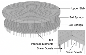
Both foundation configurations—monolithic (A) and slitted (B)—were modelled in full three dimensions using brick (hexahedral) solid elements to represent the concrete components and linear spring elements to represent the supporting soil as in
Figure 1.
4.2. Geometry Overview
Plan Dimensions: 58 m Diameter, circular footprint
Top & Bottom Slabs: 700 mm thick each
Column Grid: 700 mm × 700 mm × 1000 mm high columns spaced at 2.5 m c/c
Bottom Slab Slits (Config B): 25 mm wide, full depth, orthogonal between columns
4.3. Material Properties
Table 1.
Material Properties. | [8] | MIDAS FEA NX User Guide. MIDAS IT Co., Ltd. Bureau of Indian Standards. IS 456: 2000 – Plain and Reinforced Concrete: Code of Practice. BIS, New Delhi. |
Component | Property | Value |
Concrete (M30) | Young’s Modulus (E) | 30 GPa |
Poisson’s Ratio (ν) | 0.20 |
Reinforcing Steel (Fe500) | Yield Strength (fy) | 500 MPa |
Young’s Modulus | 200 GPa |
Subgrade Soil | Modulus of Subgrade Reaction (ks) | 30 MN/m³ |
4.4. Element Types and Mesh
Solid Elements: 8-node (hexahedral) brick elements used for slabs and columns
Soil Springs: One-way vertical compression springs distributed under bottom slab nodes
Mesh Refinement: Finer mesh (150mm or smaller) near slit edges and column junctions
Typical element size: 300 mm × 300 mm × 300 mm
Mesh sensitivity checks ensured convergence within ±5% in key results
Mesh Convergence
Table 2. Deflection for finite element sizes.
Element Size | Maximum Deflection |
400 mm | 18.8 mm |
300 mm | 18.3 mm |
200 mm | 18.2 mm |
4.5. Boundary Conditions
Supports:
Vertical-only elastic springs under the entire bottom slab
No lateral resistance (foundation allowed to expand laterally under load)
Symmetry: Not used due to circular plan and discontinuous features
Edge Constraints: None—entire base is loaded and reacts via soil springs
4.6. Loading Scheme
Uniform Pressure Load:
150 kPa applied over the top slab area
Represents full tank liquid load, including steel shell weight and base pressure
Load Duration: Assumed static; no time-dependent effects considered
Self-Weight: Included via gravity loading
4.7. Modelling of Slits and Shear Dowels (Configuration B)
Slits were explicitly modelled as 25 mm wide full-depth gaps in the bottom slab, orthogonal in layout.
Interface elements introduced across slits to simulate dowel action.
Shear dowels modelled as:
Discrete nonlinear spring elements resisting shear across slit planes.
Assigned stiffness values based on 16 mm diameter rebars spaced at 200 mm.
No moment or axial transfer allowed across the slit.
The shear stiffness of dowel connectors was estimated based on elastic shear deformation of reinforcing bars using classical dowel theory, considering bar diameter, spacing, and steel modulus. The assigned spring stiffness therefore represents an equivalent shear transfer capacity across the slit interfaces.
4.8. Assumptions and Limitations
All materials considered as linear elastic, except dowels, for this comparative study.
Nonlinear material behaviour and full stress–strain evolution were not considered in the present study since the objective of the analysis is comparative evaluation of foundation configurations under service-level loading.
Cracking, crushing, or reinforcement yielding not explicitly modelled.
Soil behaviour idealized as Winkler type; no consolidation or plasticity included.
No tank uplift considered.
The shear stiffness of dowel connectors was estimated based on elastic shear deformation of reinforcing bars using classical dowel theory.
The analysis assumes linear elastic material behaviour for concrete and steel. In practice, tensile stresses approaching the cracking strength of concrete may lead to localized cracking near slit edges and dowel interfaces. Such nonlinear behaviour could reduce peak stresses while increasing localized deformation.
The maximum computed soil contact pressure of approximately 210 kPa remains within the typical allowable bearing capacity range for medium dense sand and stiff clay soils (200–300 kPa).
The foundation design therefore remains within practical geotechnical limits.
All contour figures now include legend scale bars indicating the numerical range of deformation contact pressure, and principal stress values.
Figure 1. Finite element mesh model.
Mesh (representative) model of foundation system, showing column grid, slab layers, and subgrade spring.
The soil–structure interaction in the present study is represented using Winkler-type elastic springs, which provide a simplified but widely accepted representation of subgrade response for comparative foundation analysis. The objective of the study is not to reproduce site-specific soil behaviour but to evaluate the relative structural performance of monolithic and slitted foundation configurations under identical support conditions. More advanced soil models incorporating continuum interaction, nonlinear soil behaviour, or time-history seismic analysis may provide additional insight but are beyond the scope of the present investigation.
4.9. Mesh Modelling
To ensure reliability of modelling assumptions, results (deflections and soil pressures) were verified against:
Analytical flat slab bending estimates
Comparative results from classical plate-on-spring models
Mesh convergence and symmetry validation
5. Results and Discussion
The clarity and quantitative interpretation of the numerical results, all deformation and stress contour plots include legend scale bars indicating the full numerical range of the plotted variables. These legends enable direct visualization of displacement magnitude, soil contact pressure distribution, and principal stress variation across the foundation system, thereby facilitating clear comparison between the monolithic and slitted configurations.
Structural Response Parameters for two configurations are shown in
Table 3.Table 3. Comparative Structural Response.
Configuration | Maximum Deflection (Static) | Maximum Deflection (Seismic) | Maximum Soil Pressure |
Configuration A (Monolithic) | 18.2 mm | 23.75 mm | 210 kPa |
Configuration B (Slitted) | 19.1 mm | 25.0 mm | 185 kPa |
The finite element models were analyzed under gravity, uniform tank load of 150 kPa, and a static equivalent lateral seismic acceleration of 0.25g. The key comparisons between Configurations A and B are summarized below.
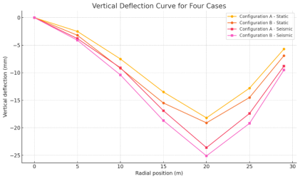
5.1. Maximum Vertical Deflection
Vertical Deflection Curves in Figure 2 Vertical Deflection Contours in Figure 3 Configuration A showed peak centre deflections of 18.2 mm, while Configuration B exhibited deflection of 19.1 mm under static load, whereas deflections were 23.75mm and 25mm respectively under seismic load. Under seismic condition the deflections increased.
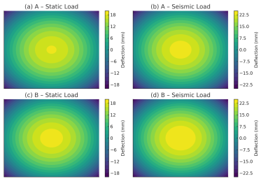
Figures (refer
Figure 3) show FEM-computed deflected shapes under both static (150 kPa) and seismic (0.25g horizontal acceleration) loading for monolithic (A) and slitted (B) configurations. Deflection scale is in mm.
(a) Configuration A – Static Load
(b) Configuration A – Seismic Load
(c) Configuration B – Static Load
(d) Configuration B – Seismic Load
The colour scale reflects vertical displacement. Peak deflection values are consistent with
Figure 2: Configuration A (18.2 mm static, 23.75 mm seismic); Configuration B (19.1 mm static, 25 mm seismic).
Also, refer to para 5.3 for more on deflection.
5.2. Stress Contours in Slabs (Refer Figure 4) Stress field pattern is studied and the results are as stated below:
Monolithic Case (A).
Static load: 150kPa.
Maximum compressive stresses below columns with peak bending stresses occurring near column lines and outer edges were noticed. Radial stress contours were noticed as smooth.
Seismic load: 0.25g, horizontal.
It induced in plane tension/compression with stress concentrations near edges and under columns and minor uplift was observed near slab periphery.
Slitted Case (B)
Static Load:
Localised stress peaks near slit ends were observed with high shear stress gradients at slit – dowel interfaces. Dowels carry shear, but moment continuity is broken.
Localised stress peaks near slit ends were noticed. Dowels carry shear, but moment continuity is broken.
Seismic Load (0.25g).
Shear stress across slits increased and stress discontinued along slit paths. Interface springs (dowels) got activated in tension / compression. However, stress intensification was noted near slit terminations and dowel locations.
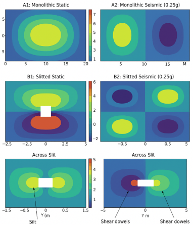
Principal Stress Contours in Bottom Slab for All Four Cases in Figure 4 Figure 4. Stress Contours in Bottom Slab (All Four Cases).
While gaps represent orthogonal slits; shear dowels not shown but modelled in interface zones.
Subfigures, in
Figure 4, show principal stress contours (in MPa) in the bottom slab under static and seismic loading for monolithic (A) and slitted (B) configurations.
(a) Configuration A – Static Load
(b) Configuration A – Seismic Load (0.25g)
(c) Configuration B – Static Load
(d) Configuration B – Seismic Load (0.25g)
Stress concentrations are observed near column-slab interfaces and along slit-dowel regions under seismic conditions (0.25g), with redistribution evident in slitted configurations. Refer para at end of the section for detailed interpretation.
The seismic configurations (A2 and B2) are each represented by two contour plots in
Figure 4. This is necessary to illustrate orthogonal stress components and depth-dependent variations, particularly in the presence of discontinuities such as slits and nonlinear spring elements.
Observations on the stress contour maps are as below:
For A2, the continuous slab experiences elevated tensile stress concentrations near the periphery and below the tank wall interface. These are influenced by the horizontal seismic acceleration (0.25g) and the slab’s rigidity.
In B2, the discontinuous slab behaviour causes stress redistribution. Local peaks arise at dowel interfaces, where relative movement between slab sectors is resisted. Despite higher local stress, the global deformation is more diffused due to reduced stiffness continuity.
The observed stress fields support the conclusion that:
Monolithic foundations distribute load more uniformly but are prone to concentrated seismic effects at the slab perimeter.
Slitted foundations modify the stress paths and reduce large-scale continuity, necessitating careful dowel design but offering potential advantages in seismic energy dissipation.
Table 4. Principal Stress Contours in Bottom Slab for all four cases.
Sub figure | Configuration | Load Condition | Description |
a | A1-monolithic | Static Load (150kPa) | Radial Flexural tension peaks between columns; smooth symmetric field |
b | A2-monolithic | Seismic Load (0.25g) | Increased peripheral tensile stress; higher shear at column-slab junctions |
c | B1- Slitted | Static Load (150kPa) | Localised stress near stilts and dowels; reduced global continuity |
d | B2- Stilted | Seismic Load (0.25g) | Stress amplification at slit-dowel regions; redistribution across slab sectors |
In the table below are stated Principal Stress Values:
Table 5. Principal stress Evaluation in Bottom Slab (all Configurations).
Case | Configuration & Load | Max Principal Stress (MPa approx.) | Critical Stress Zones |
A1 | Monolithic-static Load | 2.0 – 2.5 | Central slab panels between columns (flexural tension) |
A2 | Monolithic- Seismic Load | 3.2 – 3.6 | Column-slab junctions and slab periphery (bending and shear zones) |
B1 | Slitted – Static Load | 1.8 – 2.2 | Along slit edges and near dowels ((localized shear) |
B2 | Slitted- Seismic Load | 3.5 – 4.2 | Across slit- dowel interfaces and slab boundaries |
The introduction of orthogonal slits in the bottom slab substantially reduces the flexural continuity and redistributes internal stress fields. While the monolithic slab configuration develops smooth radial stress gradients, the slitted slab exhibits localized shear concentrations around slit edges, especially under seismic excitation. FEM results reveal that dowel action across slits helps partially recover shear stiffness but cannot replicate monolithic bending continuity. Peak stress fields shift from global bending to local shear behaviour in the slitted case.
5.3. Soil Pressure Distribution
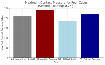
Soil pressure on the foundation bottom is shown in Figure 5: Figure 5. Contact Pressures at the bottom of foundation.
Base contact pressures in Configuration A1 showed edge concentration due to slab restraint, with localized high-pressure zones up to 210 kPa. In Configuration B1, the contact pressure was more uniform, with peaks limited to 185 kPa. In case B2 the contact pressure observed was 200kPa, lower than that of A2.
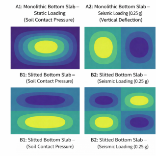
Soil contact pressure and vertical deflection contours for four bottom slab configurations under static and seismic loading conditions in Figure 6. Figure 6. Presents contour plots for contact pressure distribution and vertical deflection shapes under both static and seismic loading for monolithic (A1, A2) and slitted (B1, B2) configurations.
In A1 and A2 (monolithic slab), contact pressures exhibit fairly uniform distribution across the slab footprint, with slight increase near edges and center under seismic loading (A2). The rigid connectivity maintains slab integrity, but peak pressures are higher.
In B1 and B2 (slitted slab), contact pressure contours are more irregular, especially in seismic case (B2). The presence of orthogonal slits introduces differential soil–structure interaction, resulting in more variable pressure zones, particularly near slit ends and dowel lines.
Vertical deflection plots show greater rigidity in monolithic slabs, whereas slitted slabs deform more broadly and show greater displacement near isolated slab panels. Under seismic loading, B2 shows amplified edge and mid-panel movements, consistent with reduced slab continuity.
Overall, the inclusion of slits leads to redistribution of contact forces and increased slab flexibility, which may improve resilience against differential settlement but requires careful dowel detailing to manage stress transfer.
5.4. Seismic Response
Seismic lateral loading, generating water sloshing effect, induced sliding tendencies in both cases. While overall base shear was similar, the slitted configuration offered marginal flexibility, reducing structural demand at connections. However, the discontinuity across the slits may prove critical under cyclic loading or if dowels are under-designed.
6. Discussion: Structural Implications, Limitations, and Applicability
The introduction of full-depth orthogonal slits in the bottom slab represents a deliberate departure from the conventional assumption that continuity of foundation elements is always structurally optimal for large-diameter storage tanks. The present study demonstrates that such articulation fundamentally alters the stiffness distribution and load-transfer mechanism of the double-slab foundation system. Rather than functioning as a uniformly continuous raft, the slitted configuration behaves as a semi-articulated structural system in which flexural continuity is intentionally reduced while shear continuity is maintained through discrete dowel action. The term semi-articulated system refers to a structural configuration where flexural continuity is interrupted but limited shear transfer is maintained through dowel connectors.
Under uniform static loading, the articulated foundation exhibits a reduction in peak stress concentrations within the bottom slab and a more uniform distribution of contact pressures at the soil–foundation interface. This behaviour may be attributed to controlled stiffness modulation, which limits the development of large bending moments and promotes redistribution of load through the slab–column assembly. In this context, articulation acts as a stress-relief mechanism rather than an inherent structural deficiency. Such behaviour may be beneficial in settlement-sensitive soils where uniformity of subgrade pressure governs performance.
However, the reduction in global stiffness associated with slab segmentation introduces important limitations. Finite element results indicate increased sensitivity to horizontal seismic excitation when compared with the monolithic configuration, particularly in terms of relative displacement demands and stress concentration at shear-transfer locations. This confirms that articulated foundations cannot be regarded as direct substitutes for continuous rafts in seismic regions without supplementary stiffening or enhanced energy-dissipation mechanisms. The results therefore reinforce established seismic design principles rather than challenge them.
Shear transfer across the slits is governed by dowel action, resulting in localised stress concentrations in the vicinity of slab discontinuities. While these stresses remain within acceptable limits for the loading cases examined, they emphasise the critical importance of dowel detailing, confinement reinforcement, and realistic modelling of interface stiffness. The study demonstrates that shear continuity is redistributed rather than eliminated, shifting design emphasis from slab continuity to interface behaviour.
Soil–structure interaction analysis further indicates that the articulated system performs favourably under uniform soil conditions but may be more vulnerable to non-uniform subgrade stiffness or asymmetric loading. In such cases, the inherent redundancy and stiffness of the monolithic slab provide superior robustness. Consequently, the articulated configuration should be regarded as a conditional design option, suitable only where loading symmetry, soil uniformity, and deformation compatibility can be reasonably assured.
Finally, it is emphasised that the present study is analytical in nature and does not propose a construction-ready solution. Current design codes do not explicitly address articulated tank foundations; accordingly, the results are best interpreted within a performance-based design framework. The findings provide behavioural insight rather than prescriptive guidance and offer a rational basis for further refinement, experimental validation, and project-specific application.
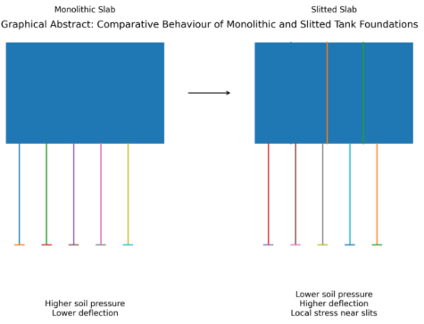
A Graphical abstract of idealized-schematic of the foundation system is shown in Figure 7 Figure 7. Graphical Abstract: - Conceptual comparison between monolithic and slitted double-slab tank foundations. The slitted configuration reduces peak soil contact pressure and redistributes foundation reactions, but introduces increased flexibility and localized stresses near slit–dowel interfaces.
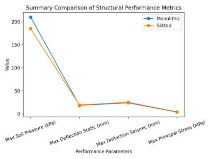
A performance summary of structural parameters is shown in Figure 8 Figure 8. Summary comparison of structural performance matrix.
Table 6. Performance parameters.
Parameter | Monolithic | Slitted |
Maximum Deflection (Static) | 18.2 mm | 19.1 mm |
Maximum Deflection (Seismic) | 23.75 mm | 25.0 mm |
Maximum Soil Pressure | 210 kPa | 185 kPa |
Maximum Principal Stress | 3.6 MPa | 4.2 MPa |
7. Conclusions
This study revisits a historically rejected double-slab tank foundation concept incorporating full-depth orthogonal slits in the bottom slab using modern three-dimensional finite element analysis with soil–structure interaction. Based on the results obtained, the following conclusions may be drawn:
1. Full-depth orthogonal slits, when bridged by appropriately detailed shear dowels, do not necessarily result in structural inadequacy under uniform static loading.
2. The articulated configuration demonstrates reduced peak stress concentrations and improved uniformity of subgrade pressure relative to a monolithic bottom slab.
3. Slab articulation leads to a reduction in global stiffness, resulting in increased sensitivity to seismic loading and non-uniform settlement conditions.
4. Shear transfer across slab discontinuities is governed by dowel action, shifting design emphasis from slab continuity to interface detailing and confinement.
5. Monolithic double-slab foundations continue to provide superior robustness under seismic excitation and irregular soil conditions.
6. Articulated foundations should therefore be regarded as conditional systems, suitable only where loading symmetry and soil uniformity can be reasonably assured.
The study does not advocate replacement of conventional practice but provides a rational analytical framework for distinguishing circumstances under which controlled articulation may be beneficial from those where continuity remains structurally preferable.
8. Design Implications and Practical Guidance
Slab articulation may be considered as a stiffness-modulation strategy rather than an inherent weakness, provided shear continuity is reliably ensured through dowel action.
Articulated foundations may offer advantages in settlement-sensitive soils under predominantly uniform loading conditions.
Such systems are not recommended for regions of high seismicity without additional stiffening measures or explicit dynamic verification.
Dowel detailing, confinement reinforcement, and interface stiffness modelling are critical to safe performance.
Monolithic foundations remain the preferred solution where soil conditions are variable or seismic demand governs design.
9. Future Research
While this study addresses static and seismic behaviour of slitted and monolithic double-slab foundations using linear elastic FEM and Winkler-based soil modelling, further investigations are recommended to advance the understanding of such foundation systems:
Incorporation of nonlinear material behaviour, including concrete cracking, dowel yielding, and interface slip.
Detailed dynamic time-history seismic analysis to capture full cyclic effects.
Long-term differential settlement modelling considering soil consolidation effects.
Experimental validation of dowel-slit interaction through scaled laboratory testing.
Extension of analysis to larger tank sizes and varying soil profiles.
Abbreviations
FEM | Finite Element Method |
3D | Three Dimensional |
config | Configuration |
MPa | Mega Pascals |
GPA | Giga Pascals |
kPA | Kilo Pascals |
0.25g | Ground Acceleration |
EIL | Engineers India Limited |
Acknowledgments
The author gratefully acknowledges his prior professional experiences as a refinery project manager with EIL and design reviewer for overseas projects on behalf of EIL, which originally exposed him to these challenging foundation design issues. The author also wishes to recognize the various contributions of previous academic research in the fields of finite element modelling, foundation design, and soil-structure interaction which form the technical basis for this study.
Author Contributions
Vijay Kumar Khanna: Conceptualization, Data curation, Formal analysis, Funding acquisition, Investigation, Methodology, Funding acquisition, Resources, software, Supervision, Validation, Visualization, Writing – original draft, Writing – review & editing
Conflicts of Interest
The author declares there is no conflicts of interest.
References
| [1] |
Bureau of Indian Standards. IS 1893 (Part 1): 2016 – Criteria for Earthquake Resistant Design of Structures. BIS, New Delhi.
|
| [2] |
John P. Wolf, Dynamic soil-structure interaction, Prentice hall Inc., N. J., U.S.A., 1985, pp. 15–28 (basic SSI formulation).
|
| [3] |
Gazetas, G. (1991). “Formulas and Charts for Impedances of Surface and Embedded Foundations.” Journal of Geotechnical Engineering, ASCE, 117(9), pp. 1363– 1381
https://doi.org/10.1061/(ASCE)0733-9410(1991)117:9(1363)
|
| [4] |
Veletsos, A. S., & Tang, Y. (1990). Soil–Structure Interaction Effects on Seismic Response of Liquid Storage Tanks. Earthquake Engineering and Structural Dynamics, 19(4), pp. 473–496.
https://doi.org/10.1002/eqe.4290190402
|
| [5] |
Bowles, J. E. (1997). Foundation Analysis and Design. 5th Edition, McGraw-Hill, New York., pp 468-492.
|
| [6] |
Poulos, H. G., & Davis, E. H. (1974). Elastic Solutions for Soil and Foundations. John Wiley & Sons, New York., pp 156-175.
|
| [7] |
“Formulas and Charts for Impedances of Surface and Embedded Foundations.” Journal of Geotechnical Engineering, ASCE, 117(9), pp. 1363–1381.
|
| [8] |
MIDAS FEA NX User Guide. MIDAS IT Co., Ltd. Bureau of Indian Standards. IS 456: 2000 – Plain and Reinforced Concrete: Code of Practice. BIS, New Delhi.
|
Cite This Article
-
APA Style
Khanna, V. K. (2026). FEM Study of Double-slab Tank Foundations with and Without Bottom Slab Slits Considering Seismic Effect and Soil Structure Interaction. American Journal of Civil Engineering, 14(2), 56-66. https://doi.org/10.11648/j.ajce.20261402.12
 Copy
|
Copy
|
 Download
ACS Style
Khanna, V. K. FEM Study of Double-slab Tank Foundations with and Without Bottom Slab Slits Considering Seismic Effect and Soil Structure Interaction. Am. J. Civ. Eng. 2026, 14(2), 56-66. doi: 10.11648/j.ajce.20261402.12
Copy
|
Download
AMA Style
Khanna VK. FEM Study of Double-slab Tank Foundations with and Without Bottom Slab Slits Considering Seismic Effect and Soil Structure Interaction. Am J Civ Eng. 2026;14(2):56-66. doi: 10.11648/j.ajce.20261402.12
Copy
|
Download
-
@article{10.11648/j.ajce.20261402.12,
  author = {Vijay Kumar Khanna},
  title = {FEM Study of Double-slab Tank Foundations with and Without Bottom Slab Slits Considering Seismic Effect and Soil Structure Interaction},
  journal = {American Journal of Civil Engineering},
  volume = {14},
  number = {2},
  pages = {56-66},
  doi = {10.11648/j.ajce.20261402.12},
  url = {https://doi.org/10.11648/j.ajce.20261402.12},
  eprint = {https://article.sciencepublishinggroup.com/pdf/10.11648.j.ajce.20261402.12},
  abstract = {More than four decades ago, a double-slab reinforced concrete foundation concept for large-diameter steel storage tanks incorporating orthogonal slits in the bottom slab was proposed but not adopted because of concerns regarding structural continuity and seismic performance. With advances in finite element modelling and soil–structure interaction analysis, the structural behaviour of such an articulated foundation system can now be re-examined. This study compares two foundation configurations: (A) a conventional monolithic double-slab foundation and (B) a slitted configuration in which full-depth orthogonal slits are introduced in the bottom slab and connected through shear dowels. Three-dimensional finite element models are developed using solid elements to represent the concrete components and Winkler-type elastic springs to simulate soil support. The analysed system represents a 58 m diameter storage tank foundation subjected to a uniform pressure load of 150 kPa together with a horizontal seismic acceleration of 0.25 g. The complete structural system is modelled as one combined unit and analysed. The results indicate that the slitted configuration reduces peak soil contact pressure from approximately 210 kPa to 185 kPa, resulting in a more uniform pressure distribution under static loading. However, the associated reduction in global stiffness increases vertical deflection from 18.2 mm to 19.1 mm under static load and from 23.75 mm to 25mm under seismic loading. Stress concentrations are also observed near slit–dowel interfaces under seismic excitation. The findings demonstrate that controlled articulation of foundation slabs can modify load-transfer mechanisms and soil pressure behaviour, although its application requires careful detailing and consideration of seismic effects. The study provides analytical insight into articulated tank foundation systems and establishes a rational framework for evaluating such configurations within performance-based foundation design.},
 year = {2026}
}
Copy
|
Download
-
TY  - JOUR
T1  - FEM Study of Double-slab Tank Foundations with and Without Bottom Slab Slits Considering Seismic Effect and Soil Structure Interaction
AU  - Vijay Kumar Khanna
Y1  - 2026/03/26
PY  - 2026
N1  - https://doi.org/10.11648/j.ajce.20261402.12
DO  - 10.11648/j.ajce.20261402.12
T2  - American Journal of Civil Engineering
JF  - American Journal of Civil Engineering
JO  - American Journal of Civil Engineering
SP  - 56
EP  - 66
PB  - Science Publishing Group
SN  - 2330-8737
UR  - https://doi.org/10.11648/j.ajce.20261402.12
AB  - More than four decades ago, a double-slab reinforced concrete foundation concept for large-diameter steel storage tanks incorporating orthogonal slits in the bottom slab was proposed but not adopted because of concerns regarding structural continuity and seismic performance. With advances in finite element modelling and soil–structure interaction analysis, the structural behaviour of such an articulated foundation system can now be re-examined. This study compares two foundation configurations: (A) a conventional monolithic double-slab foundation and (B) a slitted configuration in which full-depth orthogonal slits are introduced in the bottom slab and connected through shear dowels. Three-dimensional finite element models are developed using solid elements to represent the concrete components and Winkler-type elastic springs to simulate soil support. The analysed system represents a 58 m diameter storage tank foundation subjected to a uniform pressure load of 150 kPa together with a horizontal seismic acceleration of 0.25 g. The complete structural system is modelled as one combined unit and analysed. The results indicate that the slitted configuration reduces peak soil contact pressure from approximately 210 kPa to 185 kPa, resulting in a more uniform pressure distribution under static loading. However, the associated reduction in global stiffness increases vertical deflection from 18.2 mm to 19.1 mm under static load and from 23.75 mm to 25mm under seismic loading. Stress concentrations are also observed near slit–dowel interfaces under seismic excitation. The findings demonstrate that controlled articulation of foundation slabs can modify load-transfer mechanisms and soil pressure behaviour, although its application requires careful detailing and consideration of seismic effects. The study provides analytical insight into articulated tank foundation systems and establishes a rational framework for evaluating such configurations within performance-based foundation design.
VL  - 14
IS  - 2
ER  -
Copy
|
Download