Abstract
Piped water to private houses is today normal in many countries. This thesis has demonstrated that Pompeii had piped water distributed in lead water pipes to private houses based on gravity flow already in antiquity. This modernity was introduced in the western world with pump technology after the industrial revolution, in Stockholm about 1870 AD. The water system in Pompeii is a remarkable technological achievement made in antiquity without formal scientific knowledge in hydraulics. The system in Pompeii was however not a model for water distribution in antiquity. In three other ancient cities water pipe connections to private houses are unknown or not investigated. The purpose of this article is to describe this innovation by summarizing conclusions from three studies of the water distribution system in Pompeii published by the author. The thesis has studied water systems in ancient cities not only based on archaeological remains but also on hydraulic engineering analysis. The first study investigated the route of the water system based on the water levels in the top containers and on the technical principle for gravity flow. These levels have not been discussed before. The size and orientation of the grooves in the water towers were also investigated and three not yet excavated but possible water towers were indicated. In the second study modern hydraulic analysis was used to show how balance in the system could have been achieved. The interplay between water flow and pipe dimension has not been discussed before. The third study discussed the ability of the water distribution system to supply water to all water users by introducing a calculation method for water quantities to users. This was to demonstrate how aqueduct water could reach all water users provided that the pipe dimensions were small enough. Larger pipes would have emptied the system. The conclusion is that Pompeii had piped water to private houses already in antiquity.
Keywords
Pompeii, Piped Water, Water Towers, Street Fountains, Water Quantities
1. Preamble
Water is essential for human life and the access to a sufficient water supply is a condition for the well-being and for man to survive. This was stated already by Vitruvius in his book
De architectura.
| [3] | Vitr. De Arch. Vitruvius, De architectura, translated to Swedish, Om arkitektur, tio böcker, by Birgitta Dahlgren, Stockholm 1989. |
[3]
In antiquity water was taken from wells or rivers or collected from rainfall and stored in cisterns. Pompeii and other Roman cities were supplied with water from aqueducts.Water supply to Roman cities was important not only because water was made available to the citizens but also because plenty of running water in basins and fountains were a sign for the greatness and the richness of the Roman society. The Scandinavian city of Stockholm was supplied with water from wells, lakes and rivers and the water was carried back by the citizens to their home. The water quality was low. It was dirty and unhygienic. In the year 1834 about 3400 people in Stockholm died in cholera in a city with about 80000 inhabitants at that time. The epidemic introduced a discussion in the city to build a modern water supply system with pumps, filters and cisterns. The first water purification plant in Stockholm was opened in 1861 and had a water distribution system to several street fountains for the citizens to collect from. The interest to connect water pipes to private houses was however low. During the following ten years the interest grew and about 1870 it became common that water pipes were connected to new private houses. In the beginning of the next century baths and water toilets were installed in private houses. Stockholm was slowly developing to a modern city. Almost 2000 years earlier the ancient city Pompeii had a water distribution system to baths, street fountains and private houses based on gravity flow. In this respect Pompeii was a modern city already in antiquity. This thesis will discuss the water infrastructure in Pompeii as it has been presented and published in three separate papers. The system in Pompeii was however not a model for water distribution in antiquity. In three other ancient cities systems water pipe connections to private houses are unknown or not investigated.
2. Theories and Methods
The sources for the study of the antiquity are ancient written documents or inscriptions and physical remains found in archaeological excavations. The interpretation of ancient sources are done with different methods and analyzed based on different theories. Archaeologists are searching for valuable objects to describe and explain the culture and the history of antiquity. Archaeology seems to be strongly object-oriented.
The study of ancient history is however sometimes system oriented. The study of trade and economy during antiquity for instance is system oriented. Even if gold, silver and copper coins of the same kind are found in excavations in different locations they may give an indication of trade and economy between countries, but this might not be enough to prove an hypothesis. The whole system must be analyzed with possible trade routes. Similarly, the study of infrastructure such as roads and transports must be analyzed as systems.
The study of water systems is also system oriented. The history-interested engineer is investigating how the water systems are functioning. The engineer is questioning how the different objects found in archaeological excavations were related to each other. The task is to understand how the different objects were working together to bring water from one point to another. As Tora Crouch points out in her book
Water management in ancient Greek cities: “We can confidently turn to hydraulic engineers for insight into ancient water management, since water still behaves as it always has and is to be managed as it always was.”
| [5] | Crouch 1993 Crouch, Dora P., Water management in ancient Greek cities, New York, 1993. |
[5]
The study of ancient water systems will give us insight in how these systems actually functioned and will make us understand the geometrical layout of the systems, will help us estimate the capacity of the aqueducts and pipelines and will enlighten us on the capability of the systems to fulfil the intentions of people. These questions can be studied based on engineering analysis even when archaeological evidence is uncertain and historical written documents are rare or non-existent.
| [4] | Crapper et al. 2022 Crapper, Martin, Motta, Davide, Keenan-Jones, Duncan and Monteleone, Maria, ’Hydraulic engineering analysis of Roman water infrastructure: a review of practice and possibilities, in Water History 14, 2022, pp. 5-19. |
[4]
Ancient water systems described by archaeologists will benefit from hydraulic engineering knowledge to understand how the system worked and how much water they delivered. In an article Martin Crapper
et al. call this a new interdisciplinary discourse and named it
Archaeohydrology. | [4] | Crapper et al. 2022 Crapper, Martin, Motta, Davide, Keenan-Jones, Duncan and Monteleone, Maria, ’Hydraulic engineering analysis of Roman water infrastructure: a review of practice and possibilities, in Water History 14, 2022, pp. 5-19. |
[4]
2.1. The Knowledge of Hydraulics in Antiquity
There was no formal field of hydraulics in antiquity.
| [26] | Walski 2006 Walski, Thomas M., ‘A history of water distribution’ in Journal (American Water Works Association) Vol. 98, No. 3, 2006, pp. 110-121. |
[26]
A great number of early scientists and practical engineers knew by experience the behavior of water that it always was flowing from a higher level to a lower level. It was gravity flow. Water engineering was based on rules of thumb and not so much on scientific principles.The understanding of the characteristics of water was discussed among others by the Greek mathematician Archimedes (287-212 BC) who reported on the principles of buoyancy and who developed the screw pump called the Archimedes screw.
| [26] | Walski 2006 Walski, Thomas M., ‘A history of water distribution’ in Journal (American Water Works Association) Vol. 98, No. 3, 2006, pp. 110-121. |
[26]
Another Greek mathematician Hero of Alexandria (10-70 AD) described the significance of water pressure which allowed the construction of inverted siphons to convey water across valleys
| [10] | de Feo et al. 2011 de Feo, G., Mays, Larry W. and Angelakis, A. N., ‘Water and Wastewater Management Technologies in the Ancient Greek and Roman Civilizations’, in Elsevier BV, 2011. |
[10]
down from a high level on one side of the valley and then up again on the other side of the valley.
| [21] | Mays, 2008 Mays, Larry W., ’A very brief history of hydraulic technology during antiquity’, in Environ Fluid Mech Vol 8: 4, 2008, pp. 471-484. |
[21]
The Roman architect and engineer Vitruvius lived in the first century BC and wrote ten books on architecture titled
De architectura.
| [3] | Vitr. De Arch. Vitruvius, De architectura, translated to Swedish, Om arkitektur, tio böcker, by Birgitta Dahlgren, Stockholm 1989. |
[3]
In the eighth book of his work he described how to find water and how to distribute water
| [3] | Vitr. De Arch. Vitruvius, De architectura, translated to Swedish, Om arkitektur, tio böcker, by Birgitta Dahlgren, Stockholm 1989. |
[3]
and that the first to do when a water source was found was to measure the level.
| [3] | Vitr. De Arch. Vitruvius, De architectura, translated to Swedish, Om arkitektur, tio böcker, by Birgitta Dahlgren, Stockholm 1989. |
[3]
An aqueduct should have a slope of at least half a foot per hundred, that is 0.5%.
| [3] | Vitr. De Arch. Vitruvius, De architectura, translated to Swedish, Om arkitektur, tio böcker, by Birgitta Dahlgren, Stockholm 1989. |
[3]
2.2. Hydraulic Analysis of Ancient Water Systems
The scientific explanation of hydraulics was made as late as in the middle of the eighteenth century by Daniel Bernoulli. He formulated mathematically the so-called Bernoulli’s equation saying that the pressure of any liquid running in an ideal pipe free of any friction and other losses is constant in every single point. The equation gives a relation between water pressure and water velocity.
| [26] | Walski 2006 Walski, Thomas M., ‘A history of water distribution’ in Journal (American Water Works Association) Vol. 98, No. 3, 2006, pp. 110-121. |
[26]
In gravity flow water is always running from a higher level to a lower level. It is therefore important first to investigate the water levels in all parts of a system when making a hydraulic analysis of an ancient water system. It will then be possible to find out how different objects in the system could have been interconnected. The routes of the main water pipelines could so be defined. Water in gravity flow will normally be running continuously in the aqueduct in an ancient water system. The capacity of all water containers in the city will be analyzed to investigate the balance between incoming and outgoing water quantities in all parts of the system. The water velocity will be theoretically calculated in the hydraulic analysis.
3. Water Systems in Three Ancient Cities for Comparison
This thesis will present the water distribution system inside the city of Pompeii based on archaeological remains and hydraulic engineering calculations and analysis. Water systems were designed and built from the experiences of many practical engineers understanding the flow of water. Urban hydraulic technologies appeared already in the Bronze Age in Mesopotamia and ancient Greece.
| [21] | Mays, 2008 Mays, Larry W., ’A very brief history of hydraulic technology during antiquity’, in Environ Fluid Mech Vol 8: 4, 2008, pp. 471-484. |
[21]
Sophisticated drainage systems were constructed by the Minoans in Crete ca 2500 – 1650 BC.
| [29] | Yannopoulos et al. 2017 Yannopoulos Stavros, Yapijakis Christos, Kaiafa-Saropoulo Asimina, Antoniuo George and Angelakis Andreas N., ‘History of sanitation and hygiene technologies in the Hellenic world’ in Journal of Water, Sanitation and Hygiene for Development 07.2, 2017, pp. 163-180. |
[29]
Houses, baths and flushed toilets were connected to a central drainage system. A toilet in the palace of Minos in Knossos is probably the earliest toilet in history.
| [29] | Yannopoulos et al. 2017 Yannopoulos Stavros, Yapijakis Christos, Kaiafa-Saropoulo Asimina, Antoniuo George and Angelakis Andreas N., ‘History of sanitation and hygiene technologies in the Hellenic world’ in Journal of Water, Sanitation and Hygiene for Development 07.2, 2017, pp. 163-180. |
[29]
To illustrate the development of water systems in antiquity such systems in three ancient cities will be presented. These three cities are from different periods in time with different geographical conditions and different solutions of how to supply water to a developing city with a growing population.
3.1. The Water Systems in Pergamon
First the Greek city Pergamon located in Anatolia in Asia Minor, present Turkey. A city that grew during the latest three centuries BC from a small town with ca 20000 inhabitants about 300 BC to a large city with ca 100000 inhabitants when it became a Roman colony in 133 BC. Pergamon was in the beginning located on a 300 m high hill but developed in the low plain south of the hill. The intention in this introduction is not to give a full description of the water system in Pergamon. This has already been done by Günther Garbrecht in his impressive report in his book
Die Wasserversorgung des antiken Pergamon. | [11] | Garbrecht 1987 Garbrecht, Günther, Die Wasserversorgung antiker Städte, Mainz am Rhein, 1987. |
[11]
It is here only the idea to give comments upon a few of the special features for the development of hydraulic knowledge in antiquity. The water supply to the old town of Pergamon on the hill was in the beginning based on collection of rainwater on the roofs and the storage of rainwater in cisterns.
| [19] | de Kleijn 2001 de Kleijn, G., The Water Supply of Ancient Rome, 2001. |
[19]
Garbrecht reports that totally 80 cisterns have been found in the upper part of the city.
| [11] | Garbrecht 1987 Garbrecht, Günther, Die Wasserversorgung antiker Städte, Mainz am Rhein, 1987. |
[11]
When Pergamon grew in the third century BC the water supply had to be increased. During Greek, Roman and Byzantine time the city built totally thirteen aqueducts.
| [11] | Garbrecht 1987 Garbrecht, Günther, Die Wasserversorgung antiker Städte, Mainz am Rhein, 1987. |
[11]
First the city built the Selinos-aqueduct, but this came from a low level and could only bring water to the lower part of the city. Later the Madradag-aqueduct was constructed probably in the first half of the second century BC. The water source for this aqueduct was in the Madradag mountains at a very high level, 1230 m a.s.l. (above sea level), which is more than 900 m above the level of the upper part of the old city of Pergamon. The aqueduct was 42 km long and took water to a large storage tank at a distance of 3 km from and at a level 35 higher than the level in the city.
| [11] | Garbrecht 1987 Garbrecht, Günther, Die Wasserversorgung antiker Städte, Mainz am Rhein, 1987. |
[11]
The last part of the Madradag-aqueduct was a pressurized water pipe going down over the valley and then vertically up again up to the town wall of the city.
| [11] | Garbrecht 1987 Garbrecht, Günther, Die Wasserversorgung antiker Städte, Mainz am Rhein, 1987. |
[11]
Probably the aqueduct water was supplied to a large cistern found close to the queen’s garden.
| [11] | Garbrecht 1987 Garbrecht, Günther, Die Wasserversorgung antiker Städte, Mainz am Rhein, 1987. |
[11]
The water distribution system from the large storage cistern to the water users in the old town is no longer possible to investigate.
| [11] | Garbrecht 1987 Garbrecht, Günther, Die Wasserversorgung antiker Städte, Mainz am Rhein, 1987. |
[11]
According to Garbrecht the construction of a 3 km long pressurized water pipe supplying about 30 l/s with about 200 m water pressure must be seen as a bold step in the development of new hydraulic technology in antiquity.
| [11] | Garbrecht 1987 Garbrecht, Günther, Die Wasserversorgung antiker Städte, Mainz am Rhein, 1987. |
[11]
3.2. The Water Systems in Rome
Then the city of Rome with a million inhabitants in the first century AD located on seven hills with different levels at the tops making the building of water systems difficult. The valley between the hills was a wet marsh. Early in the fourth century BC the Romans built a water drainage system to make the land suitable for living and to expand the city.
| [28] | Webster 2005 Webster, Maud, Roms vatten från antiken till i dag, Lund 2005. |
[28]
The first drainage canal was called
Cloaca Maxima and is still in use. Pliny the Elder described the drainage system of Rome as a great building achievement.
| [2] | Pliny. Nat. Hist. Plinius, Caius Secundus, Naturalis Historia XXXIII – XXXVII, translated to Swedish, Om bildkonsten, by Bengt Ellenberger, Jonsered 1997. |
[2]
The water supply system to Rom consisted of eleven large aqueducts built in the three last centuries BC and the first century AD to supply water to all parts of the city and this complicated water system has been described by a number of scholars. The Roman Sextus Julius Frontinus was as
Curator Aquarum responsible for the water supply to the city of Rome at in AD 97-103 AD, appointed by the emperor Nerva. He was an old man and had been both
praetor and
consul of Rome. Frontinus wrote
De aquae ductu urbis Romae, a description of nine of the eleven aqueducts supplying water to the city.
| [1] | Frontin. Aq. Frontinus, Sextus Julius, De aquae ductu urbis Romae, translated to German, Wasserversorgung im antiken Rom, ed. by The Frontinus Society, München 1989. |
[1]
The book is presenting details of the routes of the aqueducts from the sources to the city as well as the different levels of the aqueducts when entering the city.
| [1] | Frontin. Aq. Frontinus, Sextus Julius, De aquae ductu urbis Romae, translated to German, Wasserversorgung im antiken Rom, ed. by The Frontinus Society, München 1989. |
[1]
Five of the nine aqueducts could deliver water to any district in the city. Six of them delivered water to large, enclosed storage tanks. It has not been possible to investigate the water distribution system to the many public baths, or the pipe connections from Rome’s aqueducts to the 591 public water street fountains in the streets.
| [1] | Frontin. Aq. Frontinus, Sextus Julius, De aquae ductu urbis Romae, translated to German, Wasserversorgung im antiken Rom, ed. by The Frontinus Society, München 1989. |
[1]
Pipe connections to private houses had only a few citizens in antiquity.
| [28] | Webster 2005 Webster, Maud, Roms vatten från antiken till i dag, Lund 2005. |
[28]
Elettra Santucci has investigated the water distribution from one of Rome’s aqueducts in the so-called Rome Transformed Project by looking at the topographical levels.
| [25] | Santucci forthcoming Santucci, Elettra, Rome Transformed Project: The supply and use of water in eastern Caelian, presented in a Frontinus-seminar in June 2022, to be published. |
[25]
The aqueduct was entering the city on top of one of the seven hills in Rome, Eastern Caelian, at 50 m above sea level and was probably supplying aqueduct water to users downhill.
3.3. The Water Systems in Constantinople
Finally, the city of Constantinople will be discussed, the present city of Istanbul in Turkey. Constantinople was the capital of the East-Roman Empire from 330 AD with a million inhabitants. The city was located at low level between the Marmara Sea and the Black Sea. The water supply system to the city came from the mountains northwest if the city. Two aqueducts were constructed. The Hadrianic Line got its name after the Roman emperor
Publius Aelius Hadrianus, emperor in Rome 117-135 AD. The Valens Line named after
Flavius Julius Valens, emperor in Rome over the East Roman Empire 364-378 AD. The archaeological remains of the two aqueducts is fragmented and only a part of the Valens Line is still visible in the city.
| [19] | de Kleijn 2001 de Kleijn, G., The Water Supply of Ancient Rome, 2001. |
[19]
In the study
Water-supply infrastructure of Byzantine Constantinople the topography of the city was investigated by Ward
et al. and they have suggested new routes for the two aqueducts.
| [27] | Ward et al. 2017 b Ward, Kate, Crapper, Martin, Altug, K. and Crow, James, ‘The Byzantine cisterns of Constantinople’, in Water History 17, 2017, pp. 1499-1506. |
[27]
After arriving in the city the two aqueducts had to pass six hills before the could deliver water to the cisterns in the city. Ward
et al. suggest that the Hadrianic Line sloped down south between hills Four and Three to the 40 m level and that the Valens Line goes south already after hill Five to stay higher up at the 50 m level. Both aqueducts supply water to large storage cisterns. There were more than 200 cisterns in the city for storage of the aqueduct water. The water distribution system to baths, street fountains and users has still to be investigated.
| [27] | Ward et al. 2017 b Ward, Kate, Crapper, Martin, Altug, K. and Crow, James, ‘The Byzantine cisterns of Constantinople’, in Water History 17, 2017, pp. 1499-1506. |
[27]
3.4. Similarities Between the Water Systems in Three Ancient Cities
To make conclusions from the discussion of the water systems in only three ancient cities is of course problematic. However some similarities will be shown below. Water supply systems in ancient cities are often based on rainwater collection from roofs and saved in small cisterns in the private house or taken from wells and carried back to the private house or from collectively constructed aqueducts. The number of aqueducts is increased over time when the population is growing. Aqueducts deliver often water to large storage cisterns for collection and saving. Water distribution systems inside the cities from the large storage cisterns to the different water users are often unknown or not investigated. Water drainage systems go from the water users to streets, accumulate sometimes to channels and are flowing downhill out of the cities to rivers or to the sea.
4. The Water System in Pompeii with Piped Water to Houses
Pompeii was supplied with water from an aqueduct arriving at the highest level in the city to a distribution building located at Porta Vesuvio. In the distribution building there was an arrangement on the floor to divide the incoming water in three separate water flows. There was no storage capacity in the distribution building. Aqueduct water was continuously running through the building. Water supply in Roman cities has earlier been studied as the different water-related objects located in the city such as water towers, street fountains, public baths and private houses. The present thesis will discuss the water distribution system inside the city of Pompeii focusing on the connecting water pipes between these towers, fountains, baths and houses and thereby disclose the interplay of pipe dimensions and water quantities. Looking at the water distribution system as a number of communicating vessels from one water container to the next including the connecting water pipe between them has made it possible to estimate water quantities in all parts of the system. The water quantities in all three water pipelines will be calculated and possible water pipe dimensions will be discussed as well as estimated water quantities in all parts of the system. Finally the thesis will demonstrate how water could be delivered based on gravity flow to street fountains, public baths and private houses. Pompeii had piped water to private houses already in antiquity.
5. The Aim
The aim of this thesis is to investigate the remarkable achievement of the water distribution system in Pompeii and to demonstrate that piped water was delivered with gravity flow to street fountains, baths and private houses already in antiquity. The study will be based on own site investigations, documented archaeological finds and published research documents and using hydraulic analysis. The water supply system will be shown with the presentation of the aqueduct and the distribution building. The water distribution system will be discussed with the presentation of the three main water pipelines and the water towers to show the ability of the system to supply water to all water users. The water drainage system will only be touched upon.
6. Gravity Flow
In antiquity gravity flow was used both in aqueducts and in water pipes as discussed in the first study.
| [22] | Olsson 2015 Olsson, Richard, The water-supply system in Roman Pompeii, Thesis for a licentiate degree, Lund University 2015. |
[22]
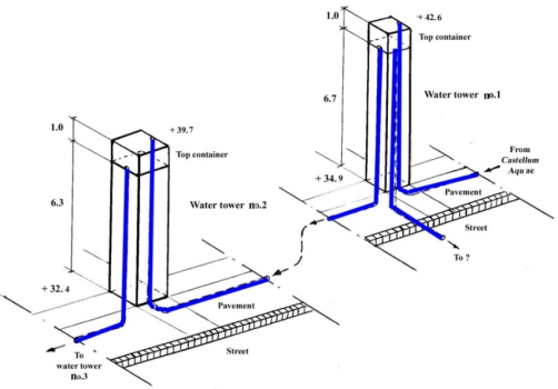
To illustrate the technical principal gravity flow, the water-pipe connection between water towers nos. 1 and 2 will be used as an example including the connecting water pipe as shown in
Figure 1 below
. The atmospheric pressure on the water surface in the top container of water tower no. 1 pressed water through the connecting water pipe up to the top container no. 2 because the water surface of this later tower was located at a lower level than that of water tower no. 1. The difference in level between two objects will make the water run in the connection.
Figure 1. Water tower nos. 1 and 2 with the connecting water pipe. Drawing by author.
The top containers were open to the atmospheric pressure at the top and thus acting as communicating vessels from one top container to the next via a connecting lead water pipe. The level at the summit of the top container was calculated by adding three figures together. The level above sea level (a.s.l.) at the street in front of each water tower was given in published research documents. The heights of the water rowers were measured in field investigations by the author. The heights of the top containers were estimated by the author.
The top containers on all the water towers in Pompeii were interconnected by the three main water pipelines. Top containers and connecting pipes were acting as a serial system of communicating vessels working together based on gravity flow.
7. The Water-supply System in Pompeii
7.1 The Aqueduct and the Distribution Building
The Serino aqueduct supplied water in a regional network to eight or nine ancient cities around the Bay of Naples and had a branch to the city of Pompeii. Duncan Keenan-Jones has studied the Serino aqueduct which he called Aqua Augusta.
| [17] | Keenan-Jones 2010 Keenan-Jones, D., ‘The Aqua Augusta and control of water resources in the Bay of Naples’, in ASCS 31 (2010), proceedings: classics.uwa.edu.au/ascs31, Perth, Australia, 2010. |
[17]
The main objective of this large aqueduct was to supply water to the Roman fleet in Misenum and to the important commercial harbor in Puteoli. It was constructed probably between 33 and 12 BC when Augustus was emperor and Marcus Agrippa was responsible for the water systems in Rome.
| [9] | de Feo & Napoli 2007 de Feo, G. and Napoli R. M. A., ‘Historical development of the Augustan Aqueduct in southern Italy: twenty centuries of works from Serino to Naples’, in WST: Tworth’s Water supply, 7, 2007. |
[9]
Christoph Ohlig is of the opinion that Pompeii was supplied with water by an earlier aqueduct from the Avella region in the Apennines. The first phase was built already in the days of Sulla and took water from the Avella region. Later in the second phase Pompeii was connected to the Serino aqueduct and got a constant supply of water all year around but with less quantity.
The aqueduct was connected to a distribution building located at
Porta Vesuvio. This building has three openings in the southern façade intended for three main water pipelines taking aqueduct water into the city. Ohlig constructed during his research a working scale model of the distribution building in Pompeii and demonstrated the model in operation at the conference
Cura Aquarum in Campania in 1994 organized by the Frontinus Society. With the model Ohlig could show that Vitruvius description of the water distribution inside the building was confusing. Vitruvius made us believe that such a distribution building should have three main outgoing water pipelines, one main pipeline should go to the street fountains, one to the public baths and the third was intended for the private users.
| [3] | Vitr. De Arch. Vitruvius, De architectura, translated to Swedish, Om arkitektur, tio böcker, by Birgitta Dahlgren, Stockholm 1989. |
[3]
Ohlig demonstrated that the three main water pipelines distributed water regionally to the eastern, central and western part of the city. The distribution building did not have any storage capacity. The aqueduct water was running continuously from the three openings in the southern façade through the three main water pipelines to small storage containers on top of the so-called water towers and to water storage tanks located on top of two large public baths. The three openings are not equal in size. Trevor Hodge measured the central opening and found it had an external diameter of 30 cm, while the two side ones have an external diameter of 25 cm.
| [14] | Hodge 1992 Hodge, Trevor, Roman Aqueducts & Water Supply, London 1992. |
[14]
He pointed out that the distribution arrangement inside the distributor building divided the incoming water from the aqueduct in three separate flows, so that most of the water came through the middle opening.
| [15] | Hodge 1996 Hodge, Trevor, ’In Vitruvium Pompeianum: Urban water distribution reappraised’, in AJA, vol. 100, No, 2, 1996, pp. 261-276. |
[15]
Less water was going to the two smaller openings. The first study by the present author has presented the route of the three water pipelines from the distributor building interconnecting all top containers on the water towers and the storage tanks on two public baths.
| [22] | Olsson 2015 Olsson, Richard, The water-supply system in Roman Pompeii, Thesis for a licentiate degree, Lund University 2015. |
[22]
The levels at the summits of all top containers must be investigated.
7.2. The Water Distribution System
In a system based on gravity flow water can only run from a higher level to a lower level. The hydraulic analysis of the system in this thesis will therefore identify the different levels above sea level (a.s.l.) for water in top containers on water towers, for water in street fountains and public baths and for water delivered to private houses and workshops. These levels have not been discussed before and will indicate how the water pipes were connected between the different objects found in archaeological excavations. The grooves on the sides of the water towers will be investigated and their orientation will indicate the directions of the three main water pipelines. The routes of the three main water pipelines will then be established by the investigation of the levels of the summits of the top containers of the water towers and of the investigation of the orientation of the grooves on the sides of the water towers.
7.3. The Levels
The starting points for the three main water pipelines were the three openings in the south façade of the distributor building
. The level in the street in front of the building has been indicated by Hans Eschebach on the city map.
| [7] | H. Eschebach 1993 Eschebach, Hans, Gebäudeverzeichnis und Stadtplan der antiken Stadt Pompeji, published by Liselotte Eschebach, Köln, 1993. |
[7]
The middle opening was supplying most of the water as shown by Hodge.
| [15] | Hodge 1996 Hodge, Trevor, ’In Vitruvium Pompeianum: Urban water distribution reappraised’, in AJA, vol. 100, No, 2, 1996, pp. 261-276. |
[15]
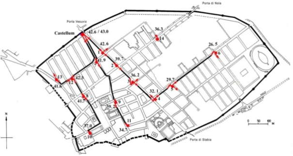
This opening was larger and at a higher level (+ 43.0 m a.s.l.) and it is anticipated that the water pipe installed through this middle opening was the beginning of the eastern main water pipeline, because most of the water demand came from water users in the eastern part of the city. The left and right openings were smaller and at a street level (+ 42.6 m a.s.l.) and intended for the western and central main water pipelines respectively. The levels at the summits of the first water tower in each of the three main water pipelines have been estimated, water tower no. 1 at + 42.6 m a.s.l., no. 7 at + 41.9 m a.s.l. and no. 12 at + 42.3 m a.s.l. These levels could in the opinion of the present author have not been much higher because they are so close to the levels at the three openings in the distributor building. The three main water pipelines are shown in
Fig. 2 below with indications of the water levels in the top containers of the water towers.
Figure 2. The routes of three main water pipelines with levels at the summit of the top containers of the water towers. Drawing by author.
The distribution of aqueduct water in the system based on gravity flow was possible when the top containers on the water towers were connected in consecutive order from a higher level to a lower level. All the top containers on the water towers in the city were supplied with aqueduct water through the three main water pipelines. Also, the water levels in two water storage tanks on top of two public baths were investigated. The water level of the summit of the storage water tank on the Stabian Baths (at + 30.8 m a.s.l.) has been calculated by the author. The water level of the summit of the possible storage water tank on top of the Forum Baths was the same as for the top container of the water tower no. 8 (at +41.7 m a.s.l.) located on the west side of the baths.
7.4. The Grooves
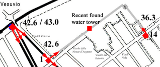
The investigation of the levels has given the order in which the top containers of the water towers were interconnected. The first study also investigated the size and the orientation of the grooves on the sides of water towers giving an indication of the direction of the main water pipelines. There were grooves on one, two or three sides of the water towers. The grooves were made to house and protect the main water pipelines. On one side of a water tower there was a groove to protect the water pipe taking water up to the top container and on another side, there was a groove to protect a pipe taking water down to be supplied to the next tower. Three grooves on a water tower indicated that there were two outgoing water pipes. In water tower no. 1 there were three grooves, one on the northern side for the main water pipe coming from the distributor building and one on the southern side for the main water pipe continuing to the next water tower no. 2. On the eastern side of water tower no. 1 there was a third groove, possibly to house a water pipe going in Vicolo delle Nozze d’Argento taking water to an unknown water tower in Regio V with a further water connection to water tower no. 14. The field investigations for the first study were made in 2009 and 2012 and the thesis was published in 2015. During 2019 new excavations were made by Italian archaeologists in Pompeii and a street and two houses were identified in Regio V. The archaeologists also found a water tower and a street fountain located in an open area close to the street crossing of Vicolo delle Nozze d’Argento and Vicolo del Balcone in insula V 8 as shown in Fig. 3 below. The new water tower is located closer to water tower no. 1 than it was predicted in the first study.
Figure 3. New water tower found close to the street crossing of Vicolo delle Nozze d’Argento and Vicolo del Balcone in insula V 8. Drawing by author.
There was a third groove also on other water towers. Water tower no. 3 has a third groove on the eastern side for a pipe going to an unknown but possible water tower in the not yet excavated parts of the city in Regio IX. Water tower no. 4 has a third groove at the northern side which according to the author possibly could have been intended to protect a pipe to supply water to the Stabian Baths. Water tower no. 5 has a third groove on the south side possibly for a connection to an unknown tower in Regio I. Water tower no. 6 is the last tower in eastern water pipeline and has three grooves. On the northern side a groove was protecting the incoming water pipe from water tower no. 5. The groove on the southern side possibly had a pipe going south to the pool in Palestra Grande. The groove on the western side of the water tower still has a pipe fragment in situ but the reason for this pipe is not known.
7.5. The Routes of the Main Water Pipelines
The first study has presented a new interpretation of the routes for the three main water pipelines by investigating the levels in the system and the orientation of the grooves. Other scholars have had different ideas about the routes and these opinions have been shown unlikely by the author in the first study.
| [22] | Olsson 2015 Olsson, Richard, The water-supply system in Roman Pompeii, Thesis for a licentiate degree, Lund University 2015. |
[22]
Liselotte Eschebach believed that the third main water pipeline was going in the eastern pavement of
Via del Vesuvio in her article
Wasserwirtschaft in Pompeji | [8] | L. Eschebach 1996 Eschebach, Liselotte, ‘Wasserwirtschaft in Pompeji’, in Cura Aquarum in Campania 1994, ed. by Nathalie de Haan & Gemma Jansen, Leiden 1996, pp. 1-12. |
[8]
but her hypothesis has not been possible to verify. Andrea Schmölder-Veit has presented a different hypothesis that the third water pipeline was first going to water tower no.7 and then continued to water tower no. 12 but this is unlikely due to the levels at the summits of the top containers as presented in this thesis. Duncan Keenan-Jones has discussed the water supply of Pompeii in an article
Somma-Vesuvian Ground movements and the water supply of Pompeii and the Bay of Naples. | [18] | Keenan-Jones 2015 Keenan-Jones, Duncan, ‘Somma-Vesuvian ground movements and the water supply of Pompeii and the bay of Naples’, in AJA, vol. 19, No. 2, 2015, pp. 191-215. |
[18]
He presented the idea that the water installations were made at various times and has presented three phases of the distribution system.
| [18] | Keenan-Jones 2015 Keenan-Jones, Duncan, ‘Somma-Vesuvian ground movements and the water supply of Pompeii and the bay of Naples’, in AJA, vol. 19, No. 2, 2015, pp. 191-215. |
[18]
Keenan-Jones has also suggested that there were only two main water pipelines connected through the two smaller openings and that the largest opening supplied water to a basin directly below it.
| [18] | Keenan-Jones 2015 Keenan-Jones, Duncan, ‘Somma-Vesuvian ground movements and the water supply of Pompeii and the bay of Naples’, in AJA, vol. 19, No. 2, 2015, pp. 191-215. |
[18]
His hypothesis is unlikely. This central hole is the largest of the three and if it had been connected directly to a basin most of the water would have been supplied to this basin and only smaller water quantities would have been supplied to the two main pipelines.
8. The Balance in the Water Distribution System
Aqueduct water was distributed in Pompeii from one top container to the next top container at a lower level based on gravity flow. The technology of inverted siphons or communicating vessels was known by experience in antiquity and had been used for aqueducts crossing over valleys and in pressurized water pipes as shown above in the Greek city of Pergamon. The use of top containers on water towers in Pompeii was a new challenge being to control the balance of the system. A top container had a double function. It should take most of the incoming water through the top container and deliver it to the next top container. At the same time, it should distribute a small amount of water to street fountains and private houses located near-by. The investigation of the balance in the water distribution system was presented in the second study to demonstrate that the water flows in to and out from a top container had to be controlled in a system with interconnected top containers in consecutive order.
| [23] | Olsson 2020 Olsson, Richard, ‘Water quantities in three main water-pipelines in Pompeii’ in Schriftenreihe der Frontinus-gesellscahft Heft 32, Budapest 2020. |
[23]
The balance was achieved in the system using smaller and smaller dimensions of the main water pipelines down the system. The interplay between water flow and pipe dimensions has not been discussed before.
8.1. The Top Containers
The top containers of the water towers were the crucial parts of the system where balance had to be achieved and maintained. Balance was achieved in a top container, when the sum of all outgoing water flows from the top container was equal to the supplied incoming flow at the same time as the top container was full of water. This could only be attained by means of adapting the dimensions of the incoming and outgoing pipes. The incoming pipe had to be larger than the outgoing pipe to the next tower otherwise the top container would have drained empty, and the balance of the system would have collapsed. Most of the water quantity passed through the top container to the top container of the next water tower. From every top container a part of the water flow was distributed to street fountains nearby and to some privileged private houses. The capacity of the top containers has been estimated based on the measured cross-section of the water tower and the estimated height of the top container. The water quantities flowing in to and out from a top container had to be calculated to show how the balance in the system was achieved.
8.2. The Water Pipes
The outgoing water pipe from a top container continues to become the incoming water pipe to the next top container. The two top containers and the interconnecting water pipe create together a system of communicating vessels. The water distribution system in Pompeii can be described as several communicating systems after each other. Water in such a communicating system tends to settle in equilibrium creating a water velocity from the higher level towards the lower. The water will be flowing based on gravity from the first top container to the next and so on further to every top container in the city. The investigation of the balance in the water distribution system had to be made on a hypothetical level because so few facts on lead water pipes were available. The large pipe fragment found in the pavement close to water tower no. 1 has been the starting point for the discussion on balance in the second study. This pipe fragment labelled tricenaria was probably part of the eastern water pipeline between the distribution building and water tower no. 1. The water distribution system in Pompeii started in the three openings in the south façade of the distribution building and water was flowing in three main water pipelines. The eastern water pipeline was going from the middle opening through a 30-fingers water pipe, tricenaria, to the water towers in the eastern part of the city and to the Stabian Baths. The central water pipeline was going from the eastern opening through a water pipe estimated to be a 20-fingers pipe, vicenaria, to the water towers in the central part of the city. Finally, the western water pipeline was going from the western opening through a water pipe also estimated to be of size 20-fingers, vicenaria, to the water towers in the western part of the city and to the Forum Baths. It will be possible to calculate the water quantities in the beginning of three main water pipelines water pipes with estimations of the head, of the length of the pipes and of the dimensions of the pipes. The calculations will be based on of the slopes between the three openings in the distribution building and the water levels in the top containers on the three water towers nos. 1, 7 and 12 being – 0.4m, - 0.7m and -0.3 m respectively, on the measured lengths of the water pipes to these three water towers being 140 m, 150 m and 300 m respectively and on the estimated sizes of the water pipes in the first part of the three main water pipelines.
8.3. The Water Quantities
The water distribution system in Pompeii could be described as several small communicating systems based on gravity flow from one top container to the next downhill. In such a specific system the water velocity in the water pipe between two interconnected top containers can be calculated with the use of Bernoulli’s equation for fluid mechanics. The equation was presented in Appendix 1 in the second study.
| [23] | Olsson 2020 Olsson, Richard, ‘Water quantities in three main water-pipelines in Pompeii’ in Schriftenreihe der Frontinus-gesellscahft Heft 32, Budapest 2020. |
[23]
The equation was transformed and simplified to describe the specific case in Pompeii consisting of interconnected top containers. The simplified form of Bernoulli’s equation was written as follows:
(1)
where w is the water velocity in the pipe
g is the gravitational acceleration
h is the head, the difference in water level from the top container of one water tower to the next
λ is the friction factor
L is the length of the pipe
d is the inner diameter of the water pipe
ζ is the single-case loss coefficient and
n is the number of bends.
It was shown that the water quantity running in a pipe based on gravity flow was determined by three geometrical variables, the head, which is the difference in water level between one top container and the next, the length of the pipe, which is the distance between two interconnected top containers, and the diameter of the pipe.
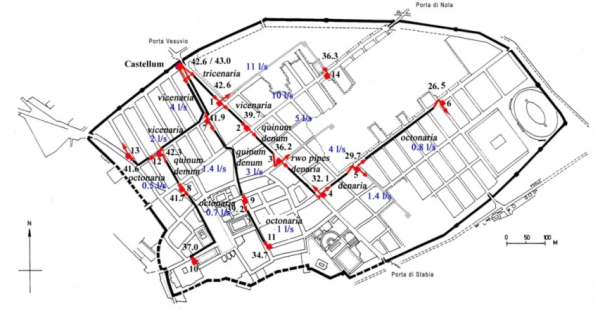
There will normally be turbulence in a water pipe causing pressure losses, partly friction losses due to the contact of the running water with the inner surface of the pipe and partly due to so-called single-case losses due to bends in the system. The friction factor in ancient lead pipes is unknown and has been estimated based on very rough modern pipes. The friction losses were large because the water pipes were very long, so large that the single-case losses were disregarded in the estimations. The calculated water velocity in the water pipe in the first part from the eastern water pipeline from the distribution building to the top container of water tower no. 1 is 0.6 m/s and the water quantity is estimated to 11 l/s.
The hypothesis that the pipelines had smaller and smaller dimensions down the system shows that most of the aqueduct water could pass through a top container and that only a part of the water quantity was distributed to water users near-by.
Figure 4. Water-supply system with possible pipe dimensions and estimated water quantities. Drawing by author modified from Laurence’s Base map; Laurence, 1994, 2.
The balance in the water distribution system has been shown by presenting possible water pipe dimensions and estimated water quantities in all parts of the three main water pipelines as well as a new estimation of the total water quantity to the city has been presented in a figure above. The total water quantity in all three water pipelines was estimated to approximately 17 l/s, far less than earlier calculations made by other scholars.
9. The Ability to Supply Piped Water to All Water Users
The investigation in the third study has been to demonstrate that aqueduct water could reach all water users, some of them at a far distance from the water towers, in a water distribution system based on gravity flow.
| [23] | Olsson 2020 Olsson, Richard, ‘Water quantities in three main water-pipelines in Pompeii’ in Schriftenreihe der Frontinus-gesellscahft Heft 32, Budapest 2020. |
[23]
The distribution of water in small lead pipes to water users has not been discussed in detail before. The ability is the capability of the water distribution system to supply water from a top container of a water tower to all water users in the city. Some were located close to a water tower but others at a far distance from a water tower. The ability can be theoretically discussed based on the total water quantity supplied to the city through the aqueduct, the locations of the water towers, the locations of the water users and the pipe dimensions. The water distribution system in Pompeii delivered aqueduct water to both public and private water users. Water was supplied through individual small pipes to public use in street fountains and public baths and to private use in houses and workshops. Water from the aqueduct was supplied to 42 street fountains, two large and three small public baths and to at least 91 or possibly 103 private houses. The third study explained the water flow in the small water pipes from the top containers to all public and private users and which priority the system gave between public and private use.
| [24] | Olsson 2024 Olsson, Richard, ‘Water quantities for public and private use in Pompeii’, in Water History, Special issue, 2024. |
[24]
A calculation method based on Bernoulli’s equation for fluid mechanics was presented. The water velocity in a pipe can be calculated considering only three geometrical variables, the head (h), the length of the pipe (L), and the inner diameter of the pipe (d). Most water users were located at a far distance from the water tower that supplied water to the user.
9.1. Water Supply to Street Fountains
Locations of the street fountains are shown by Eschebach, heights have been measured and the water levels calculated. Pipe connections were believed to be to the closest water tower. Six street fountains in the southern part of the city were supposed to have been connected to one of the unknown water towers in the not yet excavated parts of the city. Each street fountain was supplied with water through a separate pipe connection from the top container of a near-by water tower. Hans Eschebach has presented 42 street fountains found in the city indicating their location.
| [6] | H. Eschebach 1983 Eschebach, Hans, ‘Gebrauchswasserversorgung Pompejis’ in Journées d’etudes sur les aqueducs romains, ed. by J.-P. Boucher, Paris 1983. |
[6]
The present author has introduced a calculation method based on Bernoulli’s equation showing that the water velocity in a pipe can be estimated considering only three geometrical variables, the head, which is the difference in water level between the top container of a water tower and the water opening of the street fountain, the length of the water pipe, which is the measured distance down from the summit of the top container along the street and up to the water opening of the street fountain and finally the diameter of the water pipe. The estimated water quantities to street fountains have been tabled in an appendix to the third study.
| [24] | Olsson 2024 Olsson, Richard, ‘Water quantities for public and private use in Pompeii’, in Water History, Special issue, 2024. |
[24]
The calculations were made only for a 5-fingers water pipe,
quinaria. The dimension was interpreted by the author as external diameter, and he has subtracted 0.5 cm corresponding to the estimated thickness of the pipe wall to obtain the hypothetical internal diameter. The calculations were made using the figure 0.04 for the friction factor. The calculations showed that the length of the pipe had a significant influence and that water quantities to street fountains located close to a water tower were higher. There were seven street fountains located within 20 m from the water tower supplied with between 0.14 and 0.27 l/s, five fountains located at 20 – 50 m from the water tower supplied with between 0.06 and 0.13 l/s, ten located at a distance of 50 – 100 m from a tower got between 0.05 and 0.13 l/s and finally fourteen street fountains located more than 100 m away were supplied with between 0.04 and 0.08 l/s. The total estimated water quantity supplied to all street fountains was summarized to 4.2 l/s.
9.2. Water Supply to Public Baths
Archaeological excavations have found remains of five public baths in Pompeii. The Stabian Baths were established long before the Roman period and the Forum Baths built after the city became a Roman colony. Two smaller public baths were built after the Serino aqueduct was connected to the city, the Suburban Baths and the Sarno Baths. The Central Baths were still under construction at the time of the eruption of Vesuvius in AD 79. The Stabian Baths had a large water storage tank on top of the building. The water level was calculated to 30.8 m a.s.l. and it was probably supplied with aqueduct water through a pipe installed in the third groove the northern side at the water tower no. 4. With the head of 1.3 m and the length of the water pipe of 100 m the water quantity was calculated to 0.8 l/s. The storage tank could be filled with water supplied during less than 22 hours. The Forum Baths was only half the size in comparison with the Stabian Baths. The Forum Baths have been studied by Ann Olga Koloski-Ostrow and must have had a water-storage tank at the top of the building as suggested by Rudolf Pemp in his doctoral thesis.
| [20] | Koloski-Ostrow 2007 Koloski-Ostrow, Ann Olga, ‘The city baths of Pompeii and Herculaneum’ in The world of Pompeii, ed. by John J. Dobbins and Pedar W. Foss, New York 2007, pp. 224-256. |
[20]
Later the Forum Baths had a water tower no. 8 built on the west side. The water quantity was estimated to 0.2 l/s. The Suburban Baths and the Sarno Baths were both supplied with aqueduct water from water tower no. 10 with an estimated quantity of 0.1 l/s each. The water supply to the Central Baths has been discussed b Nathalie de Haan and Kurt Wallat.
| [12] | de Haan & Wallat 2006 de Haan, Nathalie & Wallat, Kurt, ‘The water supply of the Central Baths in Pompeii’, in Cura Aquarum in Ephesus. Proceedings of the 12th international congress on the history of water management and hydraulic engineering in the Mediterranean Region. Ephesus/Selcuk, October 2-10, 2004, ed. by G. Wiplinger, Leuven 2006, pp. 417-422. |
[12]
They interpreted a pillar located in the service area as a possible water tower with a water storage tank on top.
| [13] | de Haan & Wallat 2023 de Haan, Nathalie & Wallat, Kurt, ‘Die Zentralthermen (Terme Centrali) in Pompeji’, in Papers of the Royal Netherlands Institute in Rome 71, 2023. |
[13]
In May 2024 Nathalie de Haan gave a lecture confirming that the water tower might have been connected to the water distribution system. The total water quantity supplied to all for public baths was 1.2 l/s.
9.3. Water Supply with Piped Water to Private Houses
Aqueduct water for private use was delivered through individual small pipes from a top container of a water tower to houses for fountains and sometimes for kitchens and baths. In workshops water was used for the production process. Most of the houses and workshops supplied with water were located at a large distance from the water tower it was connected to. Private houses connected to the aqueduct had a complex water distributions system inside the house with distribution boxes and closing valves. The method to discuss the water quantities to houses is purely hypothetical and the calculations presented in the third study are made only from the closest water tower to the front of the house.
The number of private water users is unknown. H. Eschebach indicated that 63 houses were connected to the distribution system.
| [6] | H. Eschebach 1983 Eschebach, Hans, ‘Gebrauchswasserversorgung Pompejis’ in Journées d’etudes sur les aqueducs romains, ed. by J.-P. Boucher, Paris 1983. |
[6]
He also identified 46 workshops with large water use but without mentioning if they were connected. Gemma Jansen has in her doctoral thesis listed 91 houses including some workshops supplied with aqueduct water.
| [16] | Jansen 2002 Jansen, Gemma, Water in de Romeinse stad. Pompeji, Herculaneum, Ostia, Leuven 2002. |
[16]
The present author has compared the two studies and found twelve houses according to Eschebach not mentioned by Jansen and concluded that at least 91 + 12 (in total 103) houses could have been connected to the water distribution system.
| [24] | Olsson 2024 Olsson, Richard, ‘Water quantities for public and private use in Pompeii’, in Water History, Special issue, 2024. |
[24]
To at least be able to calculate comparable figures for water quantities supplied to private users the present author has made simplifications. The calculations were made for a small water pipe with the same dimension all the way from the water tower to the front of the house and the calculations were made only to this point knowing that the actual water quantity must have been lower inside the house.
The lengths of the pipes had a significant influence in a similar way as for street fountains and the calculations of water quantities should be seen as estimations. There were 28 houses within 50 m from the water tower supplied with an estimated water quantity of 0.11 l/s, another 22 houses located at 50 – 100 m were supplied with 0.10 l/s, 37 houses located at a distance of 100 – 200 m got 0.08 l/s and 4 houses located more than 200 m away were supplied with 0.06 l/s. All figures are approximate and actual water quantities were smaller. The total water quantity for private use in houses and workshops was estimated to 8.5 l/s about half of the total water quantity delivered by the aqueduct to the city.
9.4. The Water Drainage System from Pompeii
The drainage system has not been studied in detail. Street fountains were designed with an overflow and consequently drained to the street. Water from private houses was drained out to the street at the back of the house. The streets were cleaned by drainage water flowing to the Sarno river.
10. Summary and Conclusion
This thesis has studied the remarkable achievement to distribute water to private houses already in antiquity. The water distribution system in Pompeii has been analyzed based on archaeological remains but also on hydraulic engineering analysis. In three other ancient cities water pipe connections to private houses are unknown or not investigated.
The Serino aqueduct arrived in the city of Pompeii to a distributor building, from where the water was distributed in three main water pipelines to all water users in the city. The thesis has presented the water infrastructure in the city in three published studies. The route of the water system was investigated based on the water levels in the top containers and on the technical principle for gravity flow. These levels have not been discussed before. Three main water pipelines were distributing aqueduct water from the distributor building to containers on top of several water towers and to two public baths. The water distribution system was working based on the principle that water could flow from a top container of a water tower to the next if this was located at a lower level. The levels of the summit of the top containers of the water towers were determined enabling a new interpretation of the routes of the main water pipelines to be presented. The size and orientation of the grooves in the water towers were also investigated and three not yet excavated but possible water towers were indicated. The three main water pipelines were discussed to show how balance in the system could have been achieved. The interplay between water flow and pipe dimension has not been discussed before. Based on a large pipe fragment found close to water tower no. 1 the water quantity in the eastern water pipeline was calculated to 11 l/s. In a similar way the water quantities in the central and western water pipelines were calculated to 4 l/s and 2 l/s respectively. It was concluded that the total incoming water quantity in the aqueduct to Pompeii 17 l/s was far less than previous research has indicated. The ability of the water distribution system to supply water to all water users was discussed by introducing a calculation method for water quantities to users. This was to demonstrate how aqueduct water could reach all water users provided that the pipe dimensions were small enough. Larger pipes would have emptied the system. It was concluded that water supply to street fountains and public baths was installed but that the water pipe connection to some private users must have been a priority because about half of the total aqueduct water quantity transported to the city was intended for private use. Pompeii had piped water to private houses already in antiquity.
Author Contributions
Richard Olsson: Formal Analysis, Investigation, Methodology, Writing – original draft, Writing – review & editing
Conflicts of Interest
The author declares no conflicts of interest.
References
| [1] |
Frontin. Aq. Frontinus, Sextus Julius, De aquae ductu urbis Romae, translated to German, Wasserversorgung im antiken Rom, ed. by The Frontinus Society, München 1989.
|
| [2] |
Pliny. Nat. Hist. Plinius, Caius Secundus, Naturalis Historia XXXIII – XXXVII, translated to Swedish, Om bildkonsten, by Bengt Ellenberger, Jonsered 1997.
|
| [3] |
Vitr. De Arch. Vitruvius, De architectura, translated to Swedish, Om arkitektur, tio böcker, by Birgitta Dahlgren, Stockholm 1989.
|
| [4] |
Crapper et al. 2022 Crapper, Martin, Motta, Davide, Keenan-Jones, Duncan and Monteleone, Maria, ’Hydraulic engineering analysis of Roman water infrastructure: a review of practice and possibilities, in Water History 14, 2022, pp. 5-19.
|
| [5] |
Crouch 1993 Crouch, Dora P., Water management in ancient Greek cities, New York, 1993.
|
| [6] |
H. Eschebach 1983 Eschebach, Hans, ‘Gebrauchswasserversorgung Pompejis’ in Journées d’etudes sur les aqueducs romains, ed. by J.-P. Boucher, Paris 1983.
|
| [7] |
H. Eschebach 1993 Eschebach, Hans, Gebäudeverzeichnis und Stadtplan der antiken Stadt Pompeji, published by Liselotte Eschebach, Köln, 1993.
|
| [8] |
L. Eschebach 1996 Eschebach, Liselotte, ‘Wasserwirtschaft in Pompeji’, in Cura Aquarum in Campania 1994, ed. by Nathalie de Haan & Gemma Jansen, Leiden 1996, pp. 1-12.
|
| [9] |
de Feo & Napoli 2007 de Feo, G. and Napoli R. M. A., ‘Historical development of the Augustan Aqueduct in southern Italy: twenty centuries of works from Serino to Naples’, in WST: Tworth’s Water supply, 7, 2007.
|
| [10] |
de Feo et al. 2011 de Feo, G., Mays, Larry W. and Angelakis, A. N., ‘Water and Wastewater Management Technologies in the Ancient Greek and Roman Civilizations’, in Elsevier BV, 2011.
|
| [11] |
Garbrecht 1987 Garbrecht, Günther, Die Wasserversorgung antiker Städte, Mainz am Rhein, 1987.
|
| [12] |
de Haan & Wallat 2006 de Haan, Nathalie & Wallat, Kurt, ‘The water supply of the Central Baths in Pompeii’, in Cura Aquarum in Ephesus. Proceedings of the 12th international congress on the history of water management and hydraulic engineering in the Mediterranean Region. Ephesus/Selcuk, October 2-10, 2004, ed. by G. Wiplinger, Leuven 2006, pp. 417-422.
|
| [13] |
de Haan & Wallat 2023 de Haan, Nathalie & Wallat, Kurt, ‘Die Zentralthermen (Terme Centrali) in Pompeji’, in Papers of the Royal Netherlands Institute in Rome 71, 2023.
|
| [14] |
Hodge 1992 Hodge, Trevor, Roman Aqueducts & Water Supply, London 1992.
|
| [15] |
Hodge 1996 Hodge, Trevor, ’In Vitruvium Pompeianum: Urban water distribution reappraised’, in AJA, vol. 100, No, 2, 1996, pp. 261-276.
|
| [16] |
Jansen 2002 Jansen, Gemma, Water in de Romeinse stad. Pompeji, Herculaneum, Ostia, Leuven 2002.
|
| [17] |
Keenan-Jones 2010 Keenan-Jones, D., ‘The Aqua Augusta and control of water resources in the Bay of Naples’, in ASCS 31 (2010), proceedings: classics.uwa.edu.au/ascs31, Perth, Australia, 2010.
|
| [18] |
Keenan-Jones 2015 Keenan-Jones, Duncan, ‘Somma-Vesuvian ground movements and the water supply of Pompeii and the bay of Naples’, in AJA, vol. 19, No. 2, 2015, pp. 191-215.
|
| [19] |
de Kleijn 2001 de Kleijn, G., The Water Supply of Ancient Rome, 2001.
|
| [20] |
Koloski-Ostrow 2007 Koloski-Ostrow, Ann Olga, ‘The city baths of Pompeii and Herculaneum’ in The world of Pompeii, ed. by John J. Dobbins and Pedar W. Foss, New York 2007, pp. 224-256.
|
| [21] |
Mays, 2008 Mays, Larry W., ’A very brief history of hydraulic technology during antiquity’, in Environ Fluid Mech Vol 8: 4, 2008, pp. 471-484.
|
| [22] |
Olsson 2015 Olsson, Richard, The water-supply system in Roman Pompeii, Thesis for a licentiate degree, Lund University 2015.
|
| [23] |
Olsson 2020 Olsson, Richard, ‘Water quantities in three main water-pipelines in Pompeii’ in Schriftenreihe der Frontinus-gesellscahft Heft 32, Budapest 2020.
|
| [24] |
Olsson 2024 Olsson, Richard, ‘Water quantities for public and private use in Pompeii’, in Water History, Special issue, 2024.
|
| [25] |
Santucci forthcoming Santucci, Elettra, Rome Transformed Project: The supply and use of water in eastern Caelian, presented in a Frontinus-seminar in June 2022, to be published.
|
| [26] |
Walski 2006 Walski, Thomas M., ‘A history of water distribution’ in Journal (American Water Works Association) Vol. 98, No. 3, 2006, pp. 110-121.
|
| [27] |
Ward et al. 2017 b Ward, Kate, Crapper, Martin, Altug, K. and Crow, James, ‘The Byzantine cisterns of Constantinople’, in Water History 17, 2017, pp. 1499-1506.
|
| [28] |
Webster 2005 Webster, Maud, Roms vatten från antiken till i dag, Lund 2005.
|
| [29] |
Yannopoulos et al. 2017 Yannopoulos Stavros, Yapijakis Christos, Kaiafa-Saropoulo Asimina, Antoniuo George and Angelakis Andreas N., ‘History of sanitation and hygiene technologies in the Hellenic world’ in Journal of Water, Sanitation and Hygiene for Development 07.2, 2017, pp. 163-180.
|
Cite This Article
-
-
@article{10.11648/j.ajwse.20261203.12,
  author = {Richard Olsson},
  title = {Pompeii Had Piped Water to Houses in 30 BC Stockholm Got It About 1870 AD},
  journal = {American Journal of Water Science and Engineering},
  volume = {12},
  number = {3},
  pages = {92-104},
  doi = {10.11648/j.ajwse.20261203.12},
  url = {https://doi.org/10.11648/j.ajwse.20261203.12},
  eprint = {https://article.sciencepublishinggroup.com/pdf/10.11648.j.ajwse.20261203.12},
  abstract = {Piped water to private houses is today normal in many countries. This thesis has demonstrated that Pompeii had piped water distributed in lead water pipes to private houses based on gravity flow already in antiquity. This modernity was introduced in the western world with pump technology after the industrial revolution, in Stockholm about 1870 AD. The water system in Pompeii is a remarkable technological achievement made in antiquity without formal scientific knowledge in hydraulics. The system in Pompeii was however not a model for water distribution in antiquity. In three other ancient cities water pipe connections to private houses are unknown or not investigated. The purpose of this article is to describe this innovation by summarizing conclusions from three studies of the water distribution system in Pompeii published by the author. The thesis has studied water systems in ancient cities not only based on archaeological remains but also on hydraulic engineering analysis. The first study investigated the route of the water system based on the water levels in the top containers and on the technical principle for gravity flow. These levels have not been discussed before. The size and orientation of the grooves in the water towers were also investigated and three not yet excavated but possible water towers were indicated. In the second study modern hydraulic analysis was used to show how balance in the system could have been achieved. The interplay between water flow and pipe dimension has not been discussed before. The third study discussed the ability of the water distribution system to supply water to all water users by introducing a calculation method for water quantities to users. This was to demonstrate how aqueduct water could reach all water users provided that the pipe dimensions were small enough. Larger pipes would have emptied the system. The conclusion is that Pompeii had piped water to private houses already in antiquity.},
 year = {2026}
}
 Copy
|
Copy
|
 Download
-
TY  - JOUR
T1  - Pompeii Had Piped Water to Houses in 30 BC Stockholm Got It About 1870 AD
AU  - Richard Olsson
Y1  - 2026/09/08
PY  - 2026
N1  - https://doi.org/10.11648/j.ajwse.20261203.12
DO  - 10.11648/j.ajwse.20261203.12
T2  - American Journal of Water Science and Engineering
JF  - American Journal of Water Science and Engineering
JO  - American Journal of Water Science and Engineering
SP  - 92
EP  - 104
PB  - Science Publishing Group
SN  - 2575-1875
UR  - https://doi.org/10.11648/j.ajwse.20261203.12
AB  - Piped water to private houses is today normal in many countries. This thesis has demonstrated that Pompeii had piped water distributed in lead water pipes to private houses based on gravity flow already in antiquity. This modernity was introduced in the western world with pump technology after the industrial revolution, in Stockholm about 1870 AD. The water system in Pompeii is a remarkable technological achievement made in antiquity without formal scientific knowledge in hydraulics. The system in Pompeii was however not a model for water distribution in antiquity. In three other ancient cities water pipe connections to private houses are unknown or not investigated. The purpose of this article is to describe this innovation by summarizing conclusions from three studies of the water distribution system in Pompeii published by the author. The thesis has studied water systems in ancient cities not only based on archaeological remains but also on hydraulic engineering analysis. The first study investigated the route of the water system based on the water levels in the top containers and on the technical principle for gravity flow. These levels have not been discussed before. The size and orientation of the grooves in the water towers were also investigated and three not yet excavated but possible water towers were indicated. In the second study modern hydraulic analysis was used to show how balance in the system could have been achieved. The interplay between water flow and pipe dimension has not been discussed before. The third study discussed the ability of the water distribution system to supply water to all water users by introducing a calculation method for water quantities to users. This was to demonstrate how aqueduct water could reach all water users provided that the pipe dimensions were small enough. Larger pipes would have emptied the system. The conclusion is that Pompeii had piped water to private houses already in antiquity.
VL  - 12
IS  - 3
ER  -
Copy
|
Download





 Share This Article
 Twitter
 Linked In
 Facebook