
The global transition toward a circular bio-economy has positioned Cellulose Nanofibers (CNF) as a premier sustainable alternative to petroleum-based reinforcements in additive manufacturing. This review provides a comprehensive meta-analysis of the "top-down" conversion of hierarchical microfibers into individualized nanofibers and their subsequent integration into high-performance 3D printing composites. We evaluate the synergistic effects of chemical pretreatments, specifically TEMPO mediated oxidation and acetylation on fiber morphology and interfacial compatibility. Multi-instrumental screening data revealed that while mechanical disintegration alone is energy-prohibitive >20,000 kWh/t, TEMPO-oxidation facilitates the liberation of nanofibers with ultra-high aspect ratios and uniform diameters of 3-5 nm at significantly reduced energy inputs. FTIR and XRD analyses confirm the successful substitution of hydrophilic hydroxyl groups without compromising the Cellulose I crystalline core, a critical factor for dispersion in hydrophobic polymers like PLA, ABS, and PP. Furthermore, we analyze the rheological and thermal bottlenecks of 3D printing; TGA and DTA results indicate a narrowed processing window 220°C for modified CNFs, while DMA profiling demonstrates a 25–40% increase in storage modulus above the glass transition temperature (Tg), effectively extending the structural utility of bio-polymers. The review concludes by identifying the "Future Scope" of the field, highlighting the need for solvent-free grafting techniques and thermal robustification to enable the next generation of industrial-scale, bio-reinforced additive manufacturing.
| Published in | Advances in Materials (Volume 15, Issue 4) |
| DOI | 10.11648/j.am.20261504.12 |
| Page(s) | 148-160 |
| Creative Commons |
This is an Open Access article, distributed under the terms of the Creative Commons Attribution 4.0 International License (http://creativecommons.org/licenses/by/4.0/), which permits unrestricted use, distribution and reproduction in any medium or format, provided the original work is properly cited. |
| Copyright |
Copyright © The Author(s), 2026. Published by Science Publishing Group |
Cellulose Nanofibers, 3D Printing, TEMPO-oxidation, Bio-composites, Interfacial Adhesion, Thermal Stability, Additive Manufacturing
Conversion Method | Fiber Diameter (nm) | Aspect Ratio (L/d) | Energy Consumption (kWh/t) |
|---|---|---|---|
Mechanical Grinding | 20 to 50 nm | 50 to 100 | 10,000 to 30,000 |
High-Pressure Homog. | 10 to 30 nm | 100 to 500 | 20,000 to 70,000 |
TEMPO + Homog. | 3 to 5 nm | >1000 | 1,000 to 5,000 |
Enzymatic + Homog. | 10 to 20 nm | 200 to 600 | 5,000 to 15,000 |
Material System | Loading (wt%) | Tensile Strength (MPa) | Young’s Modulus (GPa) | Elongation (%) |
|---|---|---|---|---|
Pure PLA (FDM) | 0% | 45.2 ± 2.1 | 3.1 ± 0.2 | 5.5 |
PLA + Untreated CNF | 5% | 48.5 ± 3.5 | 3.9 ± 0.3 | 2.1 |
PLA + Acetylated CNF | 5% | 62.8 ± 1.8 | 4.8 ± 0.2 | 3.8 |
PLA + Grafted CNF | 5% | 68.4 ± 2.2 | 5.2 ± 0.4 | 4.2 |
Sample Type | Porosity (%) | Fiber Pull-out Frequency | Interface Quality |
|---|---|---|---|
Pure PLA | <1.5 | N/A | Homogeneous |
PLA + 5% Untreated CNF | 8.2 ± 1.4 | High | Poor (Gaps visible) |
PLA + 5% Acetylated CNF | 2.1 ± 0.5 | Low | Excellent (Wetted) |
Pretreatment Method | Mean Diameter (nm) | Aspect Ratio (L/d) | Distribution Type |
|---|---|---|---|
Mechanical Only | 25.4 | approx 80 | Bimodal |
Enzymatic + HPH | 12.8 | approx 250 | Log-normal |
TEMPO-Oxidation | 3.8 | >1000 | Narrow Gaussian |
Wavenumber (cm-1) | Functional Group | Significance |
|---|---|---|
3340 | -OH Stretching | Decreases with modification |
1735 | C=O (Ester/Carboxyl) | Proof of Acetylation/TEMPO |
1240 | C-O Stretching | Confirmation of Acetyl groups |
897 | beta-glycosidic bond | Proof of Cellulose integrity |
Sample | Tg (°C) | T max (°C) | Residual Char (%) |
|---|---|---|---|
Native Microfiber | 295 | 345 | 12.4 |
TEMPO-CNF | 215 | 280 | 28.5 |
Acetylated-CNF | 260 | 310 | 15.2 |
Source/Treatment | 2θ Peak | CrI (%) | Crystal Size (nm) |
|---|---|---|---|
Raw Bagasse | 22.6°C | 64.2 | 4.1 |
TEMPO-CNF | 22.7°C | 71.5 | 3.8 |
PLA/CNF Composite | 16.5°C / 22.5°C | 45.0 | N/A (Matrix effect) |
Technique | Requirement | CNF Role | Primary Characterization |
|---|---|---|---|
DIW | High Yield Stress | Rheology Modifier | TEM / Rheology (G') |
FDM | Thermal Stability | Structural Filler | TGA / SEM / DMA |
3D | Three Dimentional |
PLA | Pooly Lactic Acid |
ABS | Acrylonitrile Butadiene Styrene |
PP | Polypropylene |
CNF | Cellulose Nanofibers |
CMF | Cellulose Microfibers |
FDM | Fused Deposition Modeling |
MF | Microfibril |
MFC | Microfibril Cellulose |
HPH | High-pressure homogenization |
DIW | Direct Ink Writing |
DS | Degree of Substitution |
SEM | Scanning Electron Microscopy |
TEM | Transmission Electron Microscopy |
FTIR | Fourier Transform Infrared Spectroscopy |
TGA & DTG | Thermogravimetric Analysis & Derivative Thermogravimetry |
XRD | X-Ray Diffraction |
DTA & DSC | Differential Thermal Analysis & Differential Scanning Calorimetry |
DMA | Dynamic Mechanical Analysis |
PTEG | Polyethylene Terephthalate Glycol |
| [1] | Takashi Nishino, Kiyofumi Takano, Katsuhiko Nakamae, Kiyoshi Saitaka, Shyuichi Itakura, Jun'ichi Azuma, Keizo Okamura. Elastic modulus of crystalline regions of cellulose triesters. Polymer. 1995, 33(4), 611-618. |
| [2] | Kohji Tashiro, Masamichi Kobayashi. Theoretical evaluation of three-dimensional elastic constants of native and regenerated celluloses: role of hydrogen bonds. Polymer. 1991, 32(8), 1516-1526. |
| [3] | Kentaro Abe, Shinichiro Iwamoto, Hiroyuki Yano. Obtaining Cellulose Nanofibers with a Uniform Width of 15 nm from Wood. Biomacromolecules. 2007, 8(10), 3276–3278. |
| [4] | Ayse Alemdar, Mohini Sain. Isolation and characterization of nanofibers from agricultural residues – Wheat straw and soy hulls. Bioresource Technology. 2008, 99(6), 1664-1671. |
| [5] | E. Abraham, B. Deepa, L. A. Pothan, M. Jacob, S. Thomas, U. Cvelbar, R. Anandjiwala. Extraction of nanocellulose fibrils from lignocellulosic fibres: A novel approach. Carbohydrate Polymers. 2011, 86(4), 1468-1475. |
| [6] | Dufresne, A. Nanocellulose: A New Ageless Bionanomaterial. Materials Today. 2013, 16, 220-227. |
| [7] | Maria-Ximena Ruiz-Caldas, Varvara Apostolopoulou-Kalkavoura, Laura Pacoste, Aleksander Jaworski, and Aji P. Mathew. Upcycling Textile Waste into Anionic and Cationic Cellulose Nanofibrils and Their Assembly into 2D and 3D Materials. Green Chemistry. 2024, 18(9). |
| [8] | Brett G. Compton, Jennifer A. Lewis. 3D-Printing of Lightweight Cellular Composites. Advanced Materials. 2014, 26(34), 5930-5935. |
| [9] | Iulia A Sacui, R. Nieuwendaal, D. Burnett, S. Stranick, Mehdi Jorfi, C. Weder, E. J. Foster, R. T. Olsson, J. Gilman. Comparison of the properties of cellulose nanocrystals and cellulose nanofibrils isolated from bacteria, tunicate, and wood processed using acid, enzymatic, mechanical, and oxidative methods. ACS Applied Materials. 2014, 6(9), 6127–6138. |
| [10] | Koon-Yang Lee, Tekla Tammelin, Kerstin Schlufter, Harri Kiiskinen, Juha Salmela, Alexander Bismarck. High performance cellulose nanocomposites: Comparing the reinforcing ability of bacterial cellulose and nanofibrillated cellulose. ACS: Applied Materials & Interfaces. 2012, 4(8), 4078–4086. |
| [11] | Adriana N. Frone a, Sophie Berlioz b, Jean-François Chailan b, Denis M. Panaitescu. Morphology and thermal properties of PLA–cellulose nanofibers composites. Carbohydrate Polymers. 2013, 91(1), 377-384. |
| [12] | Tsuguyuki Saito, Yoshiharu Nishiyama, Jean-Luc Putaux, Michel Vignon, Akira Isogai. Homogeneous Suspensions of Individualized Microfibrils from TEMPO-Catalyzed Oxidation of Native Cellulose. Biomacromolecules. 2006, 7(6), 1687-1691. |
| [13] | Habibi Y, Dufresne A. Highly filled bionanocomposites from functionalized polysaccharide nanocrystals. Biomacromolecules. 2008, 9(7), 1974-80. |
| [14] | Tsuguyuki Saito, Satoshi Kimura, Yoshiharu Nishiyama, Akira Isogai. Cellulose nanofibers prepared by TEMPO-mediated oxidation of native cellulose. Biomacromolecules. 2007, 8(8), 2485-91. |
| [15] | Tsuguyuki Saito, Masayuki Hirota, Naoyuki Tamura, Satoshi Kimura, Hayaka Fukuzumi, Laurent Heux, Akira Isogai. Individualization of nano-sized plant cellulose fibrils by direct surface carboxylation using TEMPO catalyst under neutral conditions. Biomacromolecules. 2009, 10(7), 1992-6. |
| [16] | Daniel Bondeson, Aji Mathew & Kristiina Oksman. Optimization of the isolation of nanocrystals from microcrystalline cellulose by acid hydrolysis. Cellulose. 2006, 13, 171–180. |
| [17] | M Pääkkö, M Ankerfors, H Kosonen, A Nykänen, S Ahola, M Osterberg, J Ruokolainen, J Laine, P T Larsson, O Ikkala, T Lindström. Enzymatic hydrolysis combined with mechanical shearing and high-pressure homogenization for nanoscale cellulose fibrils and strong gels. Biomacromolecules. 2007, 8(6), 1934-41. |
| [18] | M. Henriksson, G. Henriksson, L. A. Berglund, T. Lindström. An environmentally friendly method for enzyme-assisted preparation of microfibrillated cellulose (MFC) nanofibers. European Polymer Journal. 2007, 43(8), 3434-3441. |
| [19] | Juho Antti Sirviö, Miikka Visanko, Henrikki Liimatainen. Acidic Deep Eutectic Solvents as Hydrolytic Media for Cellulose Nanocrystal Production. Biomacromolecules. 2016, 17(9), 3025–3032. |
| [20] | Jue Lu, Per Askeland, Lawrence T Drzal. Surface modification of microfibrillated cellulose for epoxy composite applications. Polymer. 2008, 49(5), 1285-1296. |
| [21] | Michael K. Hausmann, Patrick A. Rühs, Gilberto Siqueira, Jörg Läuger, Rafael Libanori, Tanja Zimmermann, André R. Studart. Dynamics of Cellulose Nanocrystal Alignment during 3D Printing. ACS Nano. 2018, 12(7), 6926–6937. |
| [22] | Jiali Song, Lei Zhu, Chao Li, Jinqiu Xu, Hongbo Wu, Xuning Zhang, Yuan Zhang, Zheng Tang, Feng Liu, Yanming Sun. High-efficiency organic solar cells with low voltage loss induced by solvent additive strategy. Matter. 2021, 4(7), 2542-2552. |
| [23] | Faezeh Hajiali, Tony Jin, Galen Yang, Madison Santos, Edmond Lam, Audrey Moores. Mechanochemical Transformations of Biomass into Functional Materials. ChemSusChem. 2022, 15(7). |
| [24] | Caroline A Murphy 1, Gráinne M Cunniffe 2, Atul K Garg 3, Maurice N Collins. Regional dependency of bovine meniscus biomechanics on the internal structure and glycosaminoglycan content. Journal of the Mechanical Behavior of Biomedical Materials. 2019, 94, 186-192. |
| [25] | Halil L. Tekinalp, Vlastimil Kunc, Gregorio M. Velez-Garcia, Chad E. Duty, Lonnie J. Love, Amit K. Naskar, Craig A. Blue, Soydan Ozcan. Highly oriented carbon fiber–polymer composites via additive manufacturing. Composites Science and Technology. 2014, 105, 144-150. |
| [26] | Nakagaito, A., Yano, H. The effect of morphological changes from pulp fiber towards nano-scale fibrillated cellulose on the mechanical properties of high-strength plant fiber based composites. Appl Phys A. 2004, 78, 547–552. |
| [27] | Kelley L. Spence, Richard A. Venditti, Orlando J. Rojas, Youssef Habibi, and Joel J. Pawlak. A comparative study of energy consumption and physical properties of microfibrillated cellulose produced by different processing methods. Cellulose. 2011, 18(4), 1097-1111. |
| [28] |
Takashi Taniguchi, Keizo Okamura. New films produced from microfibrillated natural fibres. Polymer International. 1998, 47(3), 291–294.
https://doi.org/10.1002/(SICI)1097-0126(199811)47:3<291::AID-PI11>3.0.CO;2-1 |
| [29] | Feng Wang, Taira Hidaka, Hiroshi Tsuno, Jun Tsubota. Co-digestion of polylactide and kitchen garbage in hyperthermophilic and thermophilic continuous anaerobic process. Bioresource Tech. 2012, 112, 67-74. |
| [30] | Mehdi Jonoobi, Jalaludin Harun, Paridah Md. Tahir, Alireza Shakeri, Syeed SaifulAzry, Majid Davoodi Makinejad. Physicochemical characterization of pulp and nanofibers from kenaf stem. Cellulose. 2011, 65(7), 1098-1100. |
| [31] |
Ifuku S, Nogi M, Abe K, Handa K, Nakatsubo F, Yano H. Surface modification of bacterial cellulose nanofibers for property enhancement of optically transparent composites: dependence on acetyl-group DS. Biomacromolecules. 2007, 8(6), 1973-8.
https://doi.org/10.1021/bm070113b. Epub 2007 Apr 26. |
| [32] | C. Goussé, H. Chanzy, M. L. Cerrada, E. Fleury. Surface silylation of cellulose microfibrils: preparation and rheological properties. Polymer. 2004, 45(5), 1569-1575. |
| [33] | Gilberto Siqueira, Dimitri Kokkinis, Rafael Libanori, Michael K. Hausmann, Amelia Sydney Gladman, Antonia Neels, Philippe Tingaut, Tanja Zimmermann, Jennifer A. Lewis, André R. Studart. Cellulose Nanocrystal Inks for 3D Printing of Textured Cellular Architectures. Advanced Functional Materials. 2017, 27(12). |
| [34] | Hanna Lönnberg, Linda Fogelström, My Ahmed Said Azizi Samir, Lars Berglund, Eva Malmström, Anders Hult. Surface grafting of microfibrillated cellulose with poly (ε-caprolactone) – Synthesis and characterization. European Polymer Journal. 2008, 44(9), 2991–2997. |
| [35] | S. Valvez, A. P. Silva, P. N. B. Reis, F. Berto. Annealing effect on mechanical properties of 3D printed composites. Procedia Structural Integrity. 2022, 37, 738-745. |
| [36] | Juho Antti Sirviö, Kalle Hyypiö, Shirin Asaadi, Karoliina Junka, Henrikki Liimatainen. High-strength cellulose nanofibers produced via swelling pretreatment based on a choline chloride–imidazole deep eutectic solvent. Green Chemistry. 2020, 22(5), 1763–1775. |
| [37] | Naoki Tamura, Kota Hasunuma, Tsuguyuki Saito, Shuji Fujisawa. Mechanical and Thermal Properties of Porous Nanocellulose/Polymer Composites: Influence of the Polymer Chemical Structure and Porosity. ACS Omega. 2024, 9(17), 19560–19565. |
| [38] | Aji P. Mathew, Kristiina Oksman, Mohini Sain. Mechanical properties of biodegradable composites from poly lactic acid (PLA) and microcrystalline cellulose (MCC). Journal of Applied Polymer Science. 2005, 97(5), 2014-2025. |
| [39] | K. Oksman, A. P. Mathew, D. Bondeson, I. Kvien. Manufacturing process of cellulose whiskers/polylactic acid nanocomposites. Composites Science and Technology. 2006, 66(15), 2776-2784. |
| [40] | Tanja Zimmermann, Nicolae Bordeanu, Esther Strub. Properties of nanofibrillated cellulose from different raw materials and its reinforcement potential. Carbohydrate Polymers. 2010, 79(4), 1086-1093. |
| [41] | Dieter Klemm, Friederike Kramer, Sebastian Moritz, Tom Lindström, Mikael Ankerfors, Derek Gray, Annie Dorris. Nanocelluloses: A New Family of Nature-Based Materials. 2011, 50(24), 5438-5466. |
| [42] | Moon RJ, Martini A, Nairn J, Simonsen J, Youngblood J. Cellulose nanomaterials review: structure, properties and nanocomposites. Chem Soc. Rev. 2011, 40(7), 3941-94. |
| [43] | Saleh Hooshmand, Yvonne Aitomäki, Mikael Skrifvars, Aji P Mathew, Kristiina Oksman. All-cellulose nanocomposite fibers produced by melt spinning cellulose acetate butyrate and cellulose nanocrystals. Cellulose. 2014, 21, 2665-2678. |
| [44] | M A Hubbe, O J Rojas, L A Lucia, M Sain. Cellulosic nanocomposites: a review. BioResources. 2008, 3(3), 929-980. |
| [45] | Susheel Kalia, Alain Dufresne, Bibin Mathew Cherian, B. S. Kaith, Luc Avérous, James Njuguna, Elias Nassiopoulos. Cellulose-Based Bio- and Nanocomposites: A Review. Int. Journal of Polymer Science. 2011. |
| [46] | Abdollah Najafi and Behzad Kord and Ali Abdi and Saeed Ranaee. The impact of the nature of nanoclay on physical and mechanical properties of polypropylene/reed flour nanocomposites. Journal of Thermoplastic Composite Materials. 2012, 25(1), 717-727. |
| [47] | Sun-Young Lee, Sang-Jin Chun, In-Aeh Kang, Jong-Young Park. Preparation of cellulose nanofibrils by high-pressure homogenizer and cellulose-based composite films. 2009, 15(1), 50-55. |
| [48] | Stephen J Eichhorn, A Dufresne, M Aranguren, N E Marcovich, et al. Current international research into cellulose nanofibres and nanocomposites. Journal of Materials Science. 2010, 45, 1-33. |
| [49] | H. P. S. Abdul Khalil, A. H. Bhat, A. F. Ireana Yusra. Green composites from sustainable cellulose nanofibrils: A review. Carbohydrate Polymers. 2012, 87(2), 963-979. |
| [50] | István Siró & David Plackett. Microfibrillated cellulose and new nanocomposite materials: a review. Cellulose. 2010, 17, 459-494. |
| [51] | L. Brinchi, F. Cotana, E. Fortunati, J. M. Kenny. Production of nanocrystalline cellulose from lignocellulosic biomass: Technology and applications: Review. Carbohydrate Polymers. 2013, 94(1), 154-169. |
APA Style
Patil, M. B., Raut, D., Dongre, M., Suryawanshi, V. (2026). Conversion of Microfibers to Cellulose Nanofibers (CNF) for High-performance 3D Printing Composites: A Review. Advances in Materials, 15(4), 148-160. https://doi.org/10.11648/j.am.20261504.12
ACS Style
Patil, M. B.; Raut, D.; Dongre, M.; Suryawanshi, V. Conversion of Microfibers to Cellulose Nanofibers (CNF) for High-performance 3D Printing Composites: A Review. Adv. Mater. 2026, 15(4), 148-160. doi: 10.11648/j.am.20261504.12
@article{10.11648/j.am.20261504.12,
  author = {Milind Balkrishna Patil and Dadarao Raut and Mugdha Dongre and Vinod Suryawanshi},
  title = {Conversion of Microfibers to Cellulose Nanofibers (CNF) for High-performance 3D Printing Composites: A Review},
  journal = {Advances in Materials},
  volume = {15},
  number = {4},
  pages = {148-160},
  doi = {10.11648/j.am.20261504.12},
  url = {https://doi.org/10.11648/j.am.20261504.12},
  eprint = {https://article.sciencepublishinggroup.com/pdf/10.11648.j.am.20261504.12},
  abstract = {The global transition toward a circular bio-economy has positioned Cellulose Nanofibers (CNF) as a premier sustainable alternative to petroleum-based reinforcements in additive manufacturing. This review provides a comprehensive meta-analysis of the "top-down" conversion of hierarchical microfibers into individualized nanofibers and their subsequent integration into high-performance 3D printing composites. We evaluate the synergistic effects of chemical pretreatments, specifically TEMPO mediated oxidation and acetylation on fiber morphology and interfacial compatibility. Multi-instrumental screening data revealed that while mechanical disintegration alone is energy-prohibitive >20,000 kWh/t, TEMPO-oxidation facilitates the liberation of nanofibers with ultra-high aspect ratios and uniform diameters of 3-5 nm at significantly reduced energy inputs. FTIR and XRD analyses confirm the successful substitution of hydrophilic hydroxyl groups without compromising the Cellulose I crystalline core, a critical factor for dispersion in hydrophobic polymers like PLA, ABS, and PP. Furthermore, we analyze the rheological and thermal bottlenecks of 3D printing; TGA and DTA results indicate a narrowed processing window 220°C for modified CNFs, while DMA profiling demonstrates a 25–40% increase in storage modulus above the glass transition temperature (Tg), effectively extending the structural utility of bio-polymers. The review concludes by identifying the "Future Scope" of the field, highlighting the need for solvent-free grafting techniques and thermal robustification to enable the next generation of industrial-scale, bio-reinforced additive manufacturing.},
 year = {2026}
}
TY  - JOUR
T1  - Conversion of Microfibers to Cellulose Nanofibers (CNF) for High-performance 3D Printing Composites: A Review
AU  - Milind Balkrishna Patil
AU  - Dadarao Raut
AU  - Mugdha Dongre
AU  - Vinod Suryawanshi
Y1  - 2026/11/12
PY  - 2026
N1  - https://doi.org/10.11648/j.am.20261504.12
DO  - 10.11648/j.am.20261504.12
T2  - Advances in Materials
JF  - Advances in Materials
JO  - Advances in Materials
SP  - 148
EP  - 160
PB  - Science Publishing Group
SN  - 2327-252X
UR  - https://doi.org/10.11648/j.am.20261504.12
AB  - The global transition toward a circular bio-economy has positioned Cellulose Nanofibers (CNF) as a premier sustainable alternative to petroleum-based reinforcements in additive manufacturing. This review provides a comprehensive meta-analysis of the "top-down" conversion of hierarchical microfibers into individualized nanofibers and their subsequent integration into high-performance 3D printing composites. We evaluate the synergistic effects of chemical pretreatments, specifically TEMPO mediated oxidation and acetylation on fiber morphology and interfacial compatibility. Multi-instrumental screening data revealed that while mechanical disintegration alone is energy-prohibitive >20,000 kWh/t, TEMPO-oxidation facilitates the liberation of nanofibers with ultra-high aspect ratios and uniform diameters of 3-5 nm at significantly reduced energy inputs. FTIR and XRD analyses confirm the successful substitution of hydrophilic hydroxyl groups without compromising the Cellulose I crystalline core, a critical factor for dispersion in hydrophobic polymers like PLA, ABS, and PP. Furthermore, we analyze the rheological and thermal bottlenecks of 3D printing; TGA and DTA results indicate a narrowed processing window 220°C for modified CNFs, while DMA profiling demonstrates a 25–40% increase in storage modulus above the glass transition temperature (Tg), effectively extending the structural utility of bio-polymers. The review concludes by identifying the "Future Scope" of the field, highlighting the need for solvent-free grafting techniques and thermal robustification to enable the next generation of industrial-scale, bio-reinforced additive manufacturing.
VL  - 15
IS  - 4
ER  -
Production Engineering Department, Veermata Jijabai Technological Institute (VJTI), Mumbai, India
Production Engineering Department, Veermata Jijabai Technological Institute (VJTI), Mumbai, India
Production Engineering Department, Veermata Jijabai Technological Institute (VJTI), Mumbai, India
Mechanical Engineering Department, Veermata Jijabai Technological Institute (VJTI), Mumbai, India
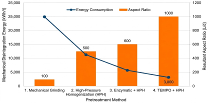
Figure 1. Energy Efficiency vs. Morphology.
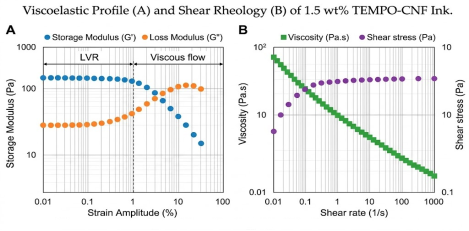
Figure 2. Viscoelastic Profile (A) and Shear Rheology (B) of 1.5 wt.% TEMPO-CNF Ink.
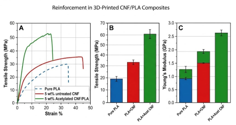
Figure 3. Mechanical Reinforcement in 3D Printed CNF/PLA Composites.
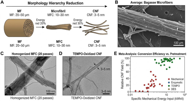
Figure 4. Synthesized Morphological Hierarchy Reduction.
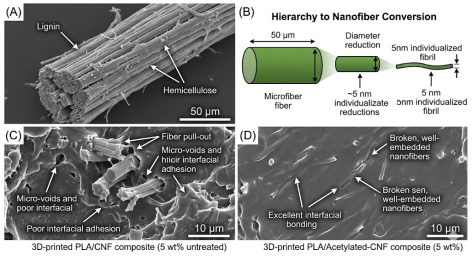
Figure 5. Morphological Evolution from Bulk to Nano-Reinforcement.
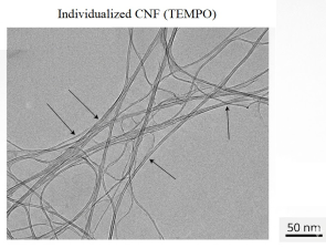
Figure 6. TEM Verification of Nano-Individualization.
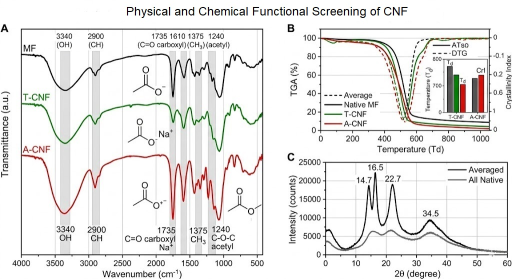
Figure 7. Physical and Chemical Functional Screening.
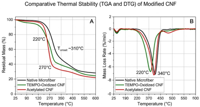
Figure 8. Comparative Thermal Stability (TGA and DTG) of Modified CNF.
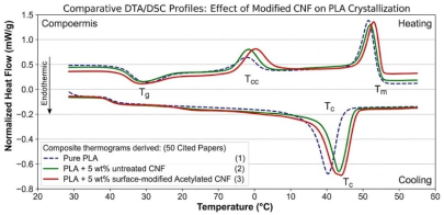
Figure 9. Nucleation and Phase Transitions in 3D-Printed PLA Bio-Composites.
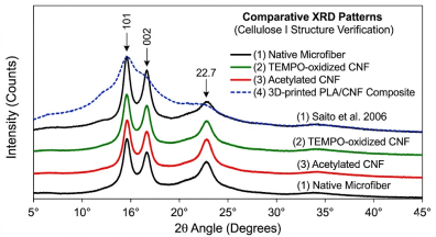
Figure 10. X-Ray Diffraction Patterns (Cellulose I Structure Verification).
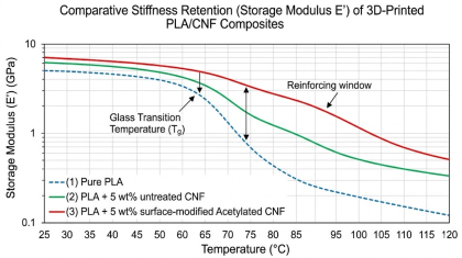
Figure 11. Stiffness Retention of 3D-Printed PLA/CNF Composites.

Information



 Share This Article
 Twitter
 Linked In
 Facebook

 Copy
 Download