
Linkage arms containing a keyed bore, forked end, pivot hole, and tapered web require coordinated datum control and machining sequence because setup transfer and local stiffness variation can degrade geometric accuracy. This study develops and experimentally evaluates a requirement-driven process-planning framework for the low-volume manufacture of a precision linkage arm from 6061-T6 aluminum alloy using three-axis computer numerical control (CNC) milling and wire electrical discharge machining (WEDM). The objective is to translate the functional requirements into an auditable chain covering datum selection, allowance distribution, tool choice, setup sequence, machining conditions, and final inspection. A single component was fabricated on a VF-1 vertical machining center. The route comprised primary and secondary face generation, staged roughing and finishing, contour milling, circular interpolation, reaming, reverse-side re-fixturing through previously machined features, chamfering, and final WEDM of the internal keyway. The principal bore was completed before WEDM to reference the keyway to the actual bore axis and retain stiffness during bulk material removal. Inspection showed that the principal bore and pivot-hole diameters and the local section thicknesses conformed to the drawing requirements. The reported parallelism deviation was 0.04 mm, while the hole-axis-to-end-face non-perpendicularity was 0.06 mm. A preliminary screening error budget indicated that primary-datum generation and reverse-side re-fixturing accounted for approximately 55–60% of these deviations, identifying setup transfer as the dominant improvement target. The results demonstrate that accuracy depended on datum continuity, controlled re-fixturing, and correct multi-process sequencing rather than on any single operation. The proposed framework provides a practical and traceable basis for low-volume linkage-component manufacture, although repeated trials, formal uncertainty analysis, surface metrology, and mechanical validation remain necessary before industrial process capability can be established.
| Published in | Engineering and Applied Sciences (Volume 11, Issue 4) |
| DOI | 10.11648/j.eas.20261104.11 |
| Page(s) | 105-114 |
| Creative Commons |
This is an Open Access article, distributed under the terms of the Creative Commons Attribution 4.0 International License (http://creativecommons.org/licenses/by/4.0/), which permits unrestricted use, distribution and reproduction in any medium or format, provided the original work is properly cited. |
| Copyright |
Copyright © The Author(s), 2026. Published by Science Publishing Group |
Linkage Arm, CNC Milling, Wire Electrical Discharge Machining, Process Planning, Dimensional Accuracy, Aluminum Alloy
Feature | Functional requirement | Primary risk | Process-planning response |
|---|---|---|---|
Central keyed bore | Shaft location and torque transfer | Bore/keyway misalignment | Finish bore before WEDM; reference keyway to bore axis |
Fork opening | Clearance and two-arm load transfer | Branch deflection and loss of parallelism | Retain stock during early cuts; finish from stable datums |
Pivot hole | Secondary rotational joint | Center-distance and axis-position error | Machine in same coordinate chain as principal bore |
Tapered body | Mass reduction with adequate stiffness | Changing stiffness during material removal | Rough before opening fork; use low finishing allowance |
Reference faces / local thicknesses | Axial assembly location | Face-to-hole perpendicularity error | Generate primary and secondary faces before precision features |
Operation | Tool/process | Tool size | Spindle speed | Feed rate | Allowance/depth |
|---|---|---|---|---|---|
First-side roughing | Flat end milling | D10 mm | 4000 rpm | 3000 mm/min | ~2.0 mm rough stock |
Semi-finishing / finishing | End milling | D8 / D6.5 | 5000 / 5539 rpm | 600 / 2309 mm/min | ~2.0 mm semi-finish; 0.2 mm finish |
Principal-bore finishing | Reaming | D16 in source route | 3000 rpm | ~100 mm/min | Final bore sizing |
Reverse-side rough/finish | End milling | D10.4 / D6.5 | 4200 / 5539 rpm | 4000 / 2309 mm/min | 0.5 mm rough; 0.2 mm finish |
Chamfering | Chamfer milling | D6 mm | 6000 rpm | ~1000 mm/min | 3 x 45° feature |
Internal keyway | Wire EDM | 0.18 mm Mo wire | — | — | 200 mm/min cutting speed |
Characteristic | Nominal/drawing requirement | Inspection result | Assessment |
|---|---|---|---|
Central bore diameter | Ø25 mm within drawing tolerance | Within specified tolerance | Conforming |
Pivot hole diameter | Ø11.8 mm within drawing tolerance | Within specified tolerance | Conforming |
Local section thicknesses | 15, 20, and 16 mm | Matched nominal drawing values | Conforming |
Parallelism of basic holes | Per drawing requirement | 0.04 mm | Acceptable |
Hole-axis-to-end-face perpendicularity | Per drawing requirement | 0.06 mm | Acceptable |
Surface roughness | Drawing-specific Ra/Rz requirement | Not fully verified for the aluminum prototype | Requires further measurement |
Internal slot/keyed-bore geometry | Drawing geometry and position | Conformed visually and dimensionally to the source drawing | Conforming |
Error source | Dominant mechanism | Parallelism allocation | Perpendicularity allocation |
|---|---|---|---|
Primary datum generation | Reference-face flatness and orientation | 0.008 mm (20%) | 0.015 mm (25%) |
Reverse-side re-fixturing | Datum transfer and locating repeatability | 0.014 mm (35%) | 0.021 mm (35%) |
Clamping and local compliance | Elastic response of the tapered body and fork | 0.008 mm (20%) | 0.009 mm (15%) |
Hole finishing and tool-axis alignment | Reaming alignment, runout, and interpolation error | 0.006 mm (15%) | 0.009 mm (15%) |
Inspection contribution | Instrument resolution and operator alignment | 0.004 mm (10%) | 0.006 mm (10%) |
Linear screening total | Allocated to the reported final deviations | 0.040 mm (100%) | 0.060 mm (100%) |
CNC | Computer Numerical Control |
WEDM | Wire Electrical Discharge Machining |
CAD | Computer-Aided Design |
CAM | Computer-Aided Manufacturing |
| [1] | A. S. Patil, V. K. Sunnapwar, K. S. Bhole, M. P. Ray, and Y. S. More, “Effective cooling methods for Ti-6Al-4V CNC milling: A review,” Advances in Materials and Processing Technologies, vol. 9, no. 2, pp. 457-506, 2023, |
| [2] | P. G. Mongan et al., “An ensemble neural network for optimising a CNC milling process,” Journal of Manufacturing Systems, vol. 71, pp. 377-389, 2023, |
| [3] | A. Equbal et al., “Evaluating CNC milling performance for machining AISI 316 stainless steel with carbide cutting tool insert,” Materials, vol. 15, no. 22, art. 8051, 2022, |
| [4] | T. T. Tung, N. T. Anh, and T. V. Minh, “Design and development of a prototype 3-axis CNC wood carving machine,” International Journal of Advanced Technology and Engineering Exploration, vol. 12, no. 125, pp. 528-541, 2025, |
| [5] | M. Soori and B. Arezoo, “Dimensional, geometrical, thermal and tool deflection errors compensation in 5-axis CNC milling operations,” Australian Journal of Mechanical Engineering, vol. 22, no. 5, pp. 935-949, 2024, |
| [6] | R. C. Reis et al., “Life cycle assessment of metal products: A comparison between wire arc additive manufacturing and CNC milling,” Advances in Industrial and Manufacturing Engineering, vol. 6, art. 100117, 2023, |
| [7] | W. Wang et al., “A state-of-the-art review on robotic milling of complex parts with high efficiency and precision,” Robotics and Computer-Integrated Manufacturing, vol. 79, art. 102436, 2023, |
| [8] | Y. Petrakov, V. Korenkov, and A. Myhovych, “Technology for programming contour milling on a CNC machine,” Eastern-European Journal of Enterprise Technologies, vol. 2, no. 1(116), pp. 55-61, 2022, |
| [9] | T. V. Minh, N. X. Quynh, N. T. Anh, and T. T. Tung, “Design and experimental study of a 4-axis CNC laser engraving machine,” Journal of Engineering Sciences, vol. 54, no. 4, pp. 272-287, 2026, |
| [10] | Z. Wang, X. Wang, X. Liu, et al., “Principle and application of the ball-end mill tool radius compensation for NURBS curve swept surfaces based on 3-axis CNC milling machines,” International Journal of Precision Engineering and Manufacturing, vol. 22, pp. 1517-1526, 2021, |
| [11] | J. Zhao and Z. Chang, “A new approach of modelling bottom-edge cutting in 4-axis rough milling of complex parts and its application on feed-rate optimization,” Micromachines, vol. 13, art. 2071, 2022, |
| [12] | T. C. Chan, J. D. Li, U. Farooq, et al., “Improving machining accuracy of complex precision turning-milling machine tools,” International Journal of Advanced Manufacturing Technology, vol. 131, pp. 211-227, 2024, |
| [13] | S. H. Mohamed Said and M. S. Abu Mansor, “A study on post processor for 5-axis CNC milling via CAD/CAM system,” in Intelligent Manufacturing and Mechatronics, Springer, 2022, pp. 451-461, |
| [14] | X. Yan, “Research and application of CNC machining method based on CAD/CAM/robot integration,” Advances in Multimedia, vol. 2022, art. 5397369, 2022, |
| [15] | L. N. Misman and M. S. Abu Mansor, “Investigation on accessible CNC simulation approaches for multi-axis milling machining through CAD/CAM,” in Intelligent Manufacturing and Mechatronics, Springer, 2024, |
| [16] | M. Dharmawardhana, A. Ratnaweera, and G. Oancea, “STEP-NC compliant intelligent CNC milling machine with an open architecture controller,” Applied Sciences, vol. 11, art. 6223, 2021, |
| [17] | D. Kučera, I. Linkeová, and M. Stejskal, “The influence of CAD model continuity on accuracy and productivity of CNC machining,” International Journal of Advanced Manufacturing Technology, vol. 124, pp. 1115-1128, 2023, |
| [18] | A. Agarwal and K. A. Desai, “Modeling of flatness errors in end milling of thin-walled components,” Proceedings of the Institution of Mechanical Engineers, Part B: Journal of Engineering Manufacture, vol. 235, no. 3, pp. 543-554, 2021, |
| [19] | G. Ge et al., “An efficient prediction method for the dynamic deformation of thin-walled parts in flank milling,” Computer-Aided Design, vol. 152, art. 103401, 2022, |
| [20] | M. Hailong, T. Aijun, X. Shubo, and L. Tong, “Finite element simulation of bending thin-walled parts and optimization of cutting parameters,” Metals, vol. 13, art. 115, 2023, |
| [21] | N. T. Anh and T. T. Tung, “Development and validation of finite element model of milling thin-walled part,” Applications in Engineering Science, vol. 25, art. 100285, 2026, |
| [22] | Z. Jia et al., “Deflection prediction of micro-milling Inconel 718 thin-walled parts,” Journal of Materials Processing Technology, vol. 291, art. 117003, 2021, |
| [23] | B. Karimi and Y. Altintas, “Hybrid modeling of position-dependent dynamics of thin-walled parts using shell elements for milling simulation,” Journal of Manufacturing Science and Engineering, vol. 144, no. 8, art. 081014, 2022, |
| [24] | S. Kurpiel, K. Zagórski, J. Cieślik, and K. Skrzypkowski, “Investigation of selected surface topography parameters and deformation during milling of vertical thin-walled structures from titanium alloy Ti6Al4V,” Materials, vol. 16, art. 3182, 2023, |
| [25] | A. A. Lassila, D. Svensson, W. Wang, et al., “Numerical evaluation of cutting strategies for thin-walled parts,” Scientific Reports, vol. 14, art. 1459, 2024, |
| [26] | M. Lin et al., “Deformation prediction in flank milling of thin-walled parts based on cutter-workpiece engagement,” Journal of Manufacturing Processes, vol. 115, pp. 375-386, 2024, |
| [27] | N. T. Anh and T. T. Tung, “Finite element and experimental investigation of up- and down-milling in thin-wall machining,” Progress in Engineering Science, vol. 3, art. 100209, 2026, |
| [28] | I. Llanos et al., “Deflection error modeling during thin-wall machining,” Procedia CIRP, vol. 117, pp. 169-174, 2023, |
| [29] | D.-M. Shi et al., “An explicit coupling model for accurate prediction of force-induced deflection in thin-walled workpiece milling,” Journal of Manufacturing Science and Engineering, vol. 144, no. 8, art. 081005, 2022, |
| [30] | Q. Sun, J. Zhou, and P. Li, “Simulations and experiments on the micro-milling process of a thin-walled structure of Al6061-T6,” Materials, vol. 15, art. 3568, 2022, |
| [31] | S. Umashankar, H. V. Manjunath, and C. S. Sumesh, “Experimental and numerical optimization of process parameters for thin wall machining of bearing housings,” Materials Today: Proceedings, vol. 46, pp. 4925-4934, 2021, |
| [32] | D. Weber et al., “Investigation on the scale effects of initial bulk and machining-induced residual stresses of thin-walled milled monolithic aluminum workpieces on part distortions,” Procedia CIRP, vol. 102, pp. 337-342, 2021, |
| [33] | D. Weber et al., “Simulation-based compensation techniques to minimize distortion of thin-walled monolithic aluminum parts due to residual stresses,” CIRP Journal of Manufacturing Science and Technology, vol. 38, pp. 427-441, 2022, |
| [34] | G. Yao and Z. Liu, “Analytical modelling for residual stress prediction in multi-step side milling of GH4169 thin-wall parts based on deformation,” Journal of Materials Research and Technology, vol. 32, pp. 1984-1995, 2024, |
| [35] | B. Li, S. N. Melkote, and S. Y. Liang, “Analysis of reactions and minimum clamping force for machining fixtures with large contact areas,” International Journal of Advanced Manufacturing Technology, vol. 16, pp. 79-84, 2000. |
| [36] | T. T. Tung, N. T. Anh, N. X. Quynh, and T. V. Minh, “Development of a machining allowance model for rectangular pocket milling operations,” Revista de Ciencias Tecnológicas, vol. 9, no. 3, art. e498, 2026, |
| [37] | M. Soori, F. K. Jough, R. Dastres, and B. Arezoo, “Robotic automation in CNC machine tools: A review,” Acta Mechanica et Automatica, vol. 18, no. 3, pp. 434-450, 2024. |
| [38] | T. T. Tung, N. X. Quynh, and T. V. Minh, “Experimental optimization of cutting parameters in flat-surface end milling using the Taguchi-desirability approach,” Engineering, Technology & Applied Science Research, vol. 16, no. 3, pp. 36693-36699, 2026, |
| [39] | K. H. Ho and S. T. Newman, “State of the art electrical discharge machining (EDM),” International Journal of Machine Tools and Manufacture, vol. 43, no. 13, pp. 1287-1300, 2003, |
APA Style
Tung, T. T., Anh, N. T., Quynh, N. X., Minh, T. V. (2026). Process Planning and Precision Fabrication of an Aluminum Linkage Arm by CNC Milling and Wire EDM. Engineering and Applied Sciences, 11(4), 105-114. https://doi.org/10.11648/j.eas.20261104.11
ACS Style
Tung, T. T.; Anh, N. T.; Quynh, N. X.; Minh, T. V. Process Planning and Precision Fabrication of an Aluminum Linkage Arm by CNC Milling and Wire EDM. Eng. Appl. Sci. 2026, 11(4), 105-114. doi: 10.11648/j.eas.20261104.11
@article{10.11648/j.eas.20261104.11,
  author = {Tran Thanh Tung and Nguyen Thi Anh and Nguyen Xuan Quynh and Tran Vu Minh},
  title = {Process Planning and Precision Fabrication of an Aluminum Linkage Arm by CNC Milling and Wire EDM},
  journal = {Engineering and Applied Sciences},
  volume = {11},
  number = {4},
  pages = {105-114},
  doi = {10.11648/j.eas.20261104.11},
  url = {https://doi.org/10.11648/j.eas.20261104.11},
  eprint = {https://article.sciencepublishinggroup.com/pdf/10.11648.j.eas.20261104.11},
  abstract = {Linkage arms containing a keyed bore, forked end, pivot hole, and tapered web require coordinated datum control and machining sequence because setup transfer and local stiffness variation can degrade geometric accuracy. This study develops and experimentally evaluates a requirement-driven process-planning framework for the low-volume manufacture of a precision linkage arm from 6061-T6 aluminum alloy using three-axis computer numerical control (CNC) milling and wire electrical discharge machining (WEDM). The objective is to translate the functional requirements into an auditable chain covering datum selection, allowance distribution, tool choice, setup sequence, machining conditions, and final inspection. A single component was fabricated on a VF-1 vertical machining center. The route comprised primary and secondary face generation, staged roughing and finishing, contour milling, circular interpolation, reaming, reverse-side re-fixturing through previously machined features, chamfering, and final WEDM of the internal keyway. The principal bore was completed before WEDM to reference the keyway to the actual bore axis and retain stiffness during bulk material removal. Inspection showed that the principal bore and pivot-hole diameters and the local section thicknesses conformed to the drawing requirements. The reported parallelism deviation was 0.04 mm, while the hole-axis-to-end-face non-perpendicularity was 0.06 mm. A preliminary screening error budget indicated that primary-datum generation and reverse-side re-fixturing accounted for approximately 55–60% of these deviations, identifying setup transfer as the dominant improvement target. The results demonstrate that accuracy depended on datum continuity, controlled re-fixturing, and correct multi-process sequencing rather than on any single operation. The proposed framework provides a practical and traceable basis for low-volume linkage-component manufacture, although repeated trials, formal uncertainty analysis, surface metrology, and mechanical validation remain necessary before industrial process capability can be established.},
 year = {2026}
}
TY  - JOUR
T1  - Process Planning and Precision Fabrication of an Aluminum Linkage Arm by CNC Milling and Wire EDM
AU  - Tran Thanh Tung
AU  - Nguyen Thi Anh
AU  - Nguyen Xuan Quynh
AU  - Tran Vu Minh
Y1  - 2026/08/10
PY  - 2026
N1  - https://doi.org/10.11648/j.eas.20261104.11
DO  - 10.11648/j.eas.20261104.11
T2  - Engineering and Applied Sciences
JF  - Engineering and Applied Sciences
JO  - Engineering and Applied Sciences
SP  - 105
EP  - 114
PB  - Science Publishing Group
SN  - 2575-1468
UR  - https://doi.org/10.11648/j.eas.20261104.11
AB  - Linkage arms containing a keyed bore, forked end, pivot hole, and tapered web require coordinated datum control and machining sequence because setup transfer and local stiffness variation can degrade geometric accuracy. This study develops and experimentally evaluates a requirement-driven process-planning framework for the low-volume manufacture of a precision linkage arm from 6061-T6 aluminum alloy using three-axis computer numerical control (CNC) milling and wire electrical discharge machining (WEDM). The objective is to translate the functional requirements into an auditable chain covering datum selection, allowance distribution, tool choice, setup sequence, machining conditions, and final inspection. A single component was fabricated on a VF-1 vertical machining center. The route comprised primary and secondary face generation, staged roughing and finishing, contour milling, circular interpolation, reaming, reverse-side re-fixturing through previously machined features, chamfering, and final WEDM of the internal keyway. The principal bore was completed before WEDM to reference the keyway to the actual bore axis and retain stiffness during bulk material removal. Inspection showed that the principal bore and pivot-hole diameters and the local section thicknesses conformed to the drawing requirements. The reported parallelism deviation was 0.04 mm, while the hole-axis-to-end-face non-perpendicularity was 0.06 mm. A preliminary screening error budget indicated that primary-datum generation and reverse-side re-fixturing accounted for approximately 55–60% of these deviations, identifying setup transfer as the dominant improvement target. The results demonstrate that accuracy depended on datum continuity, controlled re-fixturing, and correct multi-process sequencing rather than on any single operation. The proposed framework provides a practical and traceable basis for low-volume linkage-component manufacture, although repeated trials, formal uncertainty analysis, surface metrology, and mechanical validation remain necessary before industrial process capability can be established.
VL  - 11
IS  - 4
ER  -
Faculty of Engineering Mechanics and Automation, VNU University of Engineering and Technology, Hanoi, Vietnam
Faculty of Mechanical Engineering, Thuyloi University, Hanoi, Vietnam
School of Mechanical Engineering, Hanoi University of Science and Technology, Hanoi, Vietnam
School of Mechanical Engineering, Hanoi University of Science and Technology, Hanoi, Vietnam
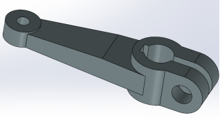
Figure 1. Three-dimensional CAD model of the mechanical linkage arm.
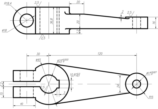
Figure 2. Technical drawing and principal dimensions of the linkage arm.
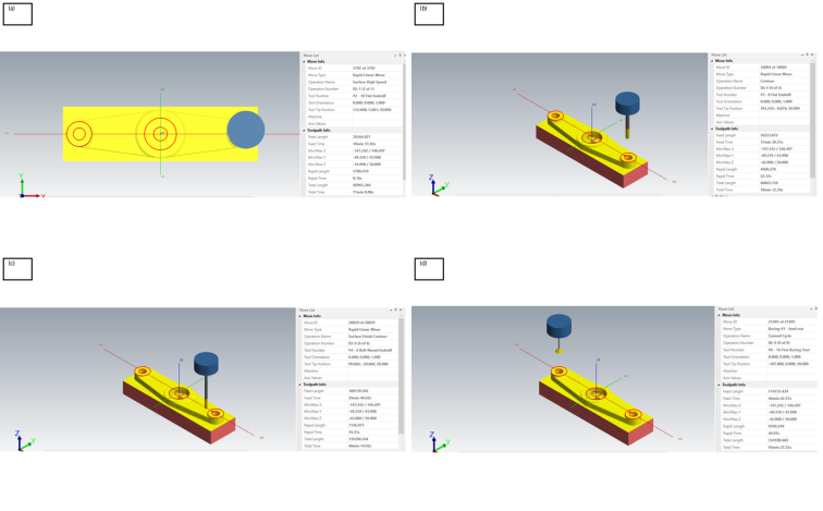
Figure 3. CAM-based machining sequence: (a) initial face roughing, (b) semi-finishing and finishing of the reference face, (c) reaming and contour generation, and (d) reverse-side machining and completion of the remaining surfaces.
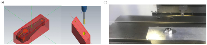
Figure 4. Machining stages of the clamp-type linkage arm: (a) CAM simulation of the hole-machining operation on the first side and (b) reverse-side setup using a threaded fastener after the primary contour and locating features had been machined.
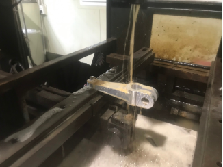
Figure 5. WEDM machining of the internal slot and keyed-bore features of the clamp-type linkage arm.
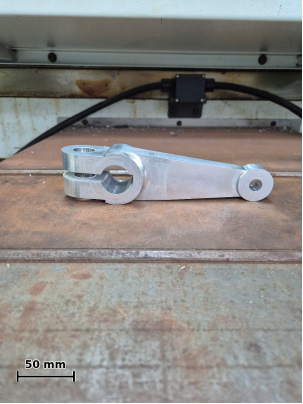
Figure 6. Completed aluminum clamp-type linkage arm after CNC milling and WEDM. The 50 mm reference scale was calibrated from the 120 mm center distance specified in Figure 2.

Information



 Share This Article
 Twitter
 Linked In
 Facebook
 Copy
Copy Download