Research Article | | Peer-Reviewed

Production of Carbon Fiber Reinforced Composites and Determination of Their Mechanical Properties

Received: 6 October 2026     Accepted: 20 October 2026     Published: 6 November 2026
Views:       Downloads:
Abstract

In this study, tensile tests of carbon fiber-based composite materials produced by compression molding and pultrusion were conducted at 0°, 45°, and 90° fiber orientations through experiments and Finite Element Analyses (FEA), and database data were obtained for the materials. In the study, plain-weave prepreg composites were used in the compression molding method, while carbon fiber yarns were used in the pultrusion method. Tensile tests were carried out on a universal testing machine in accordance with the ISO 527-4 standard. The experimental data obtained were compared with Finite Element Analyses performed in the ABAQUS CAE environment. The results showed that fiber orientation has a decisive effect on the mechanical properties of composites. It was determined that specimens taken in the 0° fiber orientation exhibited superior mechanical properties compared with specimens in the other orientations. It was observed that composites with 0° fiber orientation produced by the pultrusion method showed higher stiffness, underwent lower deformation under the same stress, and were more resistant to elastic deformation. It was evaluated that there was general agreement between the experimental results and numerical analyses, while the observed differences were caused by factors such as production-related defects, test conditions, and the ideal assumptions used in the simulations. The findings reveal that the production method and fiber layup angle are critical parameters in optimizing the mechanical properties of carbon fiber composites.

Published in International Journal of Industrial and Manufacturing Systems Engineering (Volume 11, Issue 2)
DOI 10.11648/j.ijimse.20261102.11
Page(s) 24-34
Creative Commons

This is an Open Access article, distributed under the terms of the Creative Commons Attribution 4.0 International License (http://creativecommons.org/licenses/by/4.0/), which permits unrestricted use, distribution and reproduction in any medium or format, provided the original work is properly cited.

Copyright

Copyright © The Author(s), 2026. Published by Science Publishing Group

Keywords

Carbon Fiber Composites, Compression Molding, Pultrusion, Fiber Orientation, Tensile Test, Finite Element Analysis

1. Introduction
The history of carbon fiber began in 1879 when Thomas Edison produced the first incandescent lamp filaments by carbonizing cotton thread and bamboo fibers . However, because these fibers had low mechanical strength, they were replaced by tungsten filaments at the beginning of the 20th century. The discovery of high-strength carbon fibers occurred in 1958, when Roger Bacon accidentally observed structures called carbon whiskers in a graphite arc furnace. By the 1960s, studies on different precursor materials had intensified in order to increase the efficiency of production processes. In 1960, Richard Millington developed the production process for rayon-based carbon fiber and took the first steps toward commercial carbon fiber production. However, because of the low carbon yield and limited mechanical properties of rayon, the industry turned toward more efficient alternatives . In 1961, Dr. Akio Shindo's development of polyacrylonitrile (PAN)-based carbon fibers in Japan laid the foundations of the modern composite industry. PAN-based carbon fiber production was licensed by Toray Industries in 1970, became widespread globally, and has reached a level that today constitutes approximately 90% of carbon fiber production worldwide. While carbon fiber reinforced composites were initially used only in military aviation and space projects, with decreasing production costs they have spread to a wide range of applications such as sports equipment, wind energy, and the automotive industry.
Carbon fiber is a synthetic fiber widely used in many industries because of its prominent properties such as high strength, tensile strength, light weight, high chemical and temperature resistance, and low coefficient of thermal expansion. However, the fact that these fibers are produced from non-recyclable fossil-based materials causes the composites produced with these fibers to leave a large carbon footprint in nature . Composite materials are structures formed by combining two or more different materials . From an engineering perspective, this definition can also be expressed as the combination of components within a specific design in order to keep their undesirable properties in the background while bringing desired properties, such as high strength and light weight, to the forefront. In composites, the structure consists of two main phases: the matrix and the reinforcement phase. While the matrix phase of the composite holds the fibers together and provides environmental resistance and surface integrity to the structure, the fibers forming the reinforcement phase carry the structural load, damp thermal stresses, and provide macroscopic stiffness and strength to the material.
The production of composites and the testing of their mechanical properties have always been time-consuming and costly processes. In addition, the results vary because of differences caused by production method parameters and the human factor in the composites produced for testing . However, today, computer-aided analysis programs are used to help design and analyze composite materials in a more practical, faster, and lower-cost manner. Thus, the need for experiments is reduced and different design options can be evaluated rapidly. For example, instead of expensive and time-consuming experiments, the elastic behavior of different fiber layups can be predicted with high accuracy using ANSYS/ABAQUS simulations . Monti et al. (2022) produced a polycarbonate (thermoplastic) composite component reinforced with continuous carbon fiber by one-step hybrid molding and examined it through bending tests and FEA. The FEA model correctly predicted the experimental bending load value with only a 1.6% deviation. Galati et al. (2021) compared the tensile strengths of Kevlar- and carbon fiber-based thermoplastic matrix composite specimens produced with a Markforged printer through experiments and FEA, and validated their model for different fiber layup directions. Ansari et al. (2021) conducted an experimental study and a numerical simulation to examine the mechanical properties of a hybrid kenaf/glass fiber epoxy composite material with various stacking sequences. However, the production methods of the composites used in the experimental study were not mentioned. Noman et al. (2023) modeled epoxy-matrix carbon fiber composites using ANSYS Composite PrepPost (ACP) software and performed tensile analyses in order to examine the effects of different fiber orientations on mechanical properties. Hasan Ikbal et al. (2016) used the ABAQUS/Explicit program to investigate the tensile and compressive properties of carbon and glass fiber reinforced composite materials, and reported the effectiveness of the program in examining the mechanical load behavior of composite materials. The results of the study are consistent with actual test results. Dwivedi et al. (2023) investigated the tensile behavior of carbon fiber-reinforced epoxy composites through finite element modeling. A three-dimensional model was developed to predict stress and strain distributions in multidirectional CFRP laminates. The numerical model was compared with previously published experimental results, and the authors reported the highest tensile strength for the −45° configuration.
In this study, the effects of carbon fiber-based composite materials produced by compression molding and pultrusion on the mechanical properties of the material at 0°, 45°, and 90° fiber orientations were determined, and the database data to be created for the materials were obtained. The tensile properties of the composites were tested by experiments in accordance with ISO 527 standards using a universal testing machine (Zwick) (UTM-ZW), and finite element analyses were performed using ABAQUS CAE software.
2. Materials and Methods
In this study, tensile tests and numerical analyses were performed on specimens taken at different fiber orientations from two different composites with fiber volume fractions vf of 57% and 55%. These composites, produced by compression molding and pultrusion methods, were manufactured using two different carbon-fiber based fiber sets. Tensile tests at different fiber orientations were carried out using specimens cut from the produced composites in accordance with the ISO 527-4 standard. Numerical analyses were performed using models prepared in the ABAQUS CAE environment.
2.1. Materials
For the experiments, two different fiber sets were used as fiber materials in composite production: UD (Unidirectional): SPM CF 300 UD (manufacturer: SPM, Turkey), 300 gsm (grams per square meter) and Plain Weave: SPM CF 200 P, 200 gsm. The matrix material consists of AEP 55 epoxy resin (manufacturer: Aeropreg, Turkey), 120°C Tg (glass transition temperature). The mechanical properties of the produced composites are given in Table 1.
2.2. Production of the Composites
Prepreg (pre-impregnated) fabrics and carbon fiber yarns were used in the methods employed for the production of the composites. Since prepreg fabrics contain the resin and hardener mixture required for the curing process, they are ready for layup. The composites produced by compression molding, also known as the hot press method, were made using plain-weave prepregs, while the composites produced by the pultrusion method were made using unidirectional carbon fiber yarns. The composite produced by compression molding consists of 10 layers and has a thickness of 5 mm. The composite produced by pultrusion has a width of 125 mm and a thickness of 5 mm.
2.3. Tensile Tests
The Tensile strength refers to the highest stress level that a material can withstand before fracture occurs, and this value is also closely related to how effectively load transfer from damaged fibers to intact fibers is provided through the polymer phase at the interface. The tensile test is an important characterization method that enables reliable analysis of the stress distribution created within the material by applied external forces and the variation of these stresses.
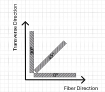
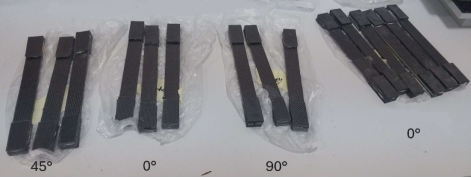
The tensile tests of the composites were carried out at the Middle East Technical University Central Laboratory using a universal testing machine (Zwick) (UTM-ZW) with specimens prepared according to ISO 527-4 standards. Tensile specimens were prepared at 0°, 45°, and 90° angles (Figure 1). The specimens were taken with dimensions of 250 x 25 mm (ISO 527-4 Type 3) and a thickness of 5 mm. End support plates (tabs) measuring 50 x 25 mm were bonded to the ends of the specimens to prevent crushing by the machine grips (Figure 2). The tests were performed at room temperature using a 250 kN load cell, with the crosshead speed set to 2 mm/min in the elastic region and 10 mm/min in the plastic region. Three samples were taken from each specimen type, the experimental results were averaged, and the mechanical properties of the composites were determined.
Table 1. Mechanical Properties of the Composites. Mechanical Properties of the Composites. Mechanical Properties of the Composites.

Properties

SPM CF 200 P / AEP 55 200 gsm (vf = %57)

SPM CF 300 UD / AEP 55 300 gsm (vf = %55)

Density (g/cm³)

1,52

1,54

Longitudinal Elastic Modulus, E11 (GPa)

60

125

Transverse Elastic Modulus, E22 (GPa)

59

8,3

Transverse Elastic Modulus, E33 (GPa)

8,2

8,3

Major Poisson's Ratio, ν12

0,05

0,31

Minor Poisson's Ratio, ν13

0,30

0,31

Minor Poisson's Ratio, ν23

0,30

0,44

Longitudinal Shear Modulus, G12 (GPa)

4,4

4,6

Transverse Shear Modulus, G13 (GPa)

3,4

4,6

Transverse Shear Modulus, G23 (GPa)

3,4

3,0

2.4. Numerical Analyses
The Finite Element Analysis (FEA) method was used to model and perform the tensile tests of the composites in a computer environment. Tensile tests were applied to each specimen type using ABAQUS CAE software. The parts used for the analysis are of the 3D Deformable shell planar type. The density, mechanical properties, and damage criteria data entered into the FEA calculations are given in Table 1. Models such as the 0°-direction specimen shown in Figure 3(a) were subjected to load in the X direction. The velocity of the point loaded in the velocity type was taken as 0.0334 mm/s to mimic the tensile test condition of 2 mm/min (Figure 3(c)). Fixed boundary conditions were added to both ends of the rectangular model, preventing movement and rotation in any direction at the ends of the model (Figure 3(b)). The mesh structure is shown in Figure 3(c). The mesh consists of 6225 S4R-type linear quadrilateral elements.
Figure 1. Fiber Orientations. Fiber Orientations.
Figure 2. Tensile Test Specimens. Tensile Test Specimens.
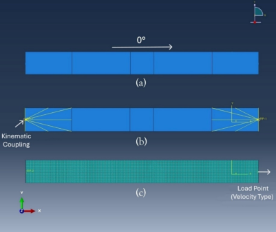
Figure 3. Load, Boundary Conditions, and Mesh Structure of the Composite Models from (a) to (c). Load, Boundary Conditions, and Mesh Structure of the Composite Models from (a) to (c).
3. Results and Discussion
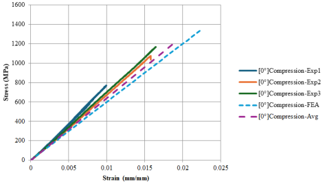
The Stress-Strain graphs obtained from the tensile tests and from the analyses performed in the computer environment are given in Figures 4-9.
When the obtained graphs are compared, it is clearly seen that fiber orientation has a major effect on tensile strength. In addition, it was observed that the strength of the composites varied according to the type of fabrics used because of the production methods. In this study, the 0° - 45° - 90° fiber orientations of the carbon fiber-based composites produced by compression and pultrusion methods were selected for the tests both because their properties under load show better results than the other orientations and because their use is more common. Fiber orientations were taken with respect to the x-axis.
In the studies conducted for composites with 0° fiber orientation produced by compression molding (Figure 4), it is observed that the data from the tensile tests and ABAQUS CAE simulations are very close to each other. In Experiment 1, the maximum stress and strain values obtained as a result of slipping of the machine grips remained lower than the other experimental data; therefore, although these data were presented in the study, they were not included in the calculation of the average material data. The average maximum stress of the materials was found from the tensile tests to be 1120 MPa, and the average maximum strain was found to be 1,612449%. In the ABAQUS CAE analysis, it was observed that the maximum stress and strain values were higher compared with the experimental data (Table 2).
Figure 4. 0°Compression Molding, Tensile Test and Analysis Stress-Strain Graph (Exp: Experiment, Avg: Average).0°Compression Molding, Tensile Test and Analysis Stress-Strain Graph (Exp: Experiment, Avg: Average).
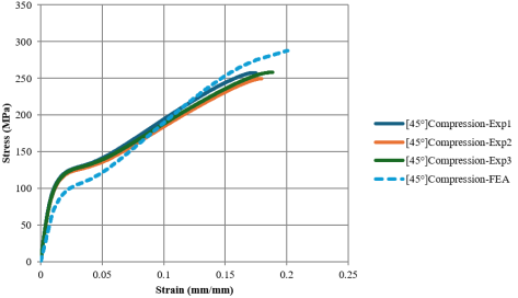
Figure 5. 45°Compression Molding, Tensile Test and Analysis Stress-Strain Grap.45°Compression Molding, Tensile Test and Analysis Stress-Strain Grap.
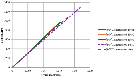
Figure 6. 90°Compression Molding, Tensile Test and Analysis Stress-Strain Graph.90°Compression Molding, Tensile Test and Analysis Stress-Strain Graph.
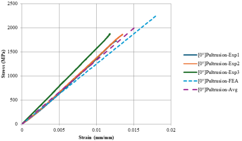
Figure 7. 0°Pultrusion, Tensile Test and Analysis Stress-Strain Grap.0°Pultrusion, Tensile Test and Analysis Stress-Strain Grap.
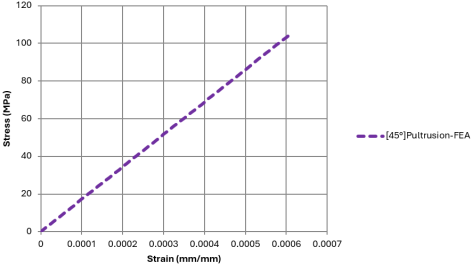
Figure 8. 45°Pultrusion, Tensile Analysis Stress-Strain Graph.45°Pultrusion, Tensile Analysis Stress-Strain Graph.
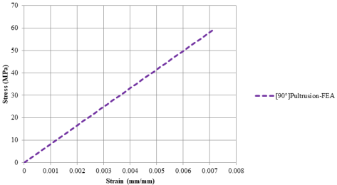
Figure 9. 90° Pultrusion, Tensile Analysis Stress-Strain Graph.90° Pultrusion, Tensile Analysis Stress-Strain Graph.
In the tensile tests of composites with 45° fiber orientation (Figure 5), the composites exhibited both elastic and plastic material behavior. In the ABAQUS CAE simulations, it was observed that the maximum stress and strain were high, while the elastic modulus was low. When the obtained data are compared, it is seen that the maximum stress and strain values are close to each other in the experiments and analyses (Table 2).
When the studies performed with 90° fiber orientation are examined (Figure 6), it is seen that the tensile tests and ABAQUS CAE simulations are compatible with each other, and that the maximum stress and strain in the analyses show higher results than the experimental data. The difference in these results is due to the presence of multiple factors affecting the tensile tests, such as human and environmental factors; in addition, the models made in the simulations are analyzed under defect-free conditions, and therefore this difference arises (Table 2).
In the experiments and analyses of composites with 0° fiber orientation produced by the pultrusion method (Figure 7), it was observed that the elastic modulus was higher in the experiments. When compared with the studies of composites produced by compression molding with the same fiber orientation, it is seen that the maximum tensile stresses are higher, the strain is lower, and the elastic moduli are more than twice those of the specimens produced by compression molding (Table 3).
The experiments at 45° and 90° fiber orientations could not be performed because specimens with dimensions suitable for the ISO-527 test standard could not be cut from the dimensions of the composites obtained by the pultrusion production method. Finite element analyses were performed for these two different fiber orientations, and the material data were obtained from these analyses (Figures 8 & 9). As expected, it was observed that the stresses and strains remained very low compared with the 0° fiber orientation (Table 3).
The average values created in Figures 4, 6, 7 are the averages of the experimental and analysis results of the materials.
Table 4 gives the average of the data obtained for 0° - 45° - 90° from the experiments and analyses of the compression molding and pultrusion methods.
Table 2. Data Obtained from Experiments and Analyses – Compression.Data Obtained from Experiments and Analyses – Compression.Data Obtained from Experiments and Analyses – Compression.

Study

Properties

0° Compression

45° Compression

90° Compression

Experiment

Average Elastic Modulus, Eavg (GPa)

65,02252

12,79918

60,27933

Experiment

Average Maximum Stress, savg (MPa)

1119,848

255,1406

925,3611

Experiment

Average Maximum Strain, eavg (%)

1,612449

17,96376

1,456871

Analysis

Elastic Modulus, E (GPa)

58,91093

7,02072

57,92901

Analysis

Maximum Stress, s (MPa)

1336,1

287,9085

1313,83

Analysis

Maximum Strain, e (%)

2,2268

20,081

2,2268

Table 3. Data Obtained from Experiments and Analyses – Pultrusion.

Study

Properties

0° Pultrusion

45° Pultrusion

90° Pultrusion

Experiment

Average Elastic Modulus, Eavg (GPa)

143,7204

-

-

Experiment

Average Maximum Stress, savg (MPa)

1811,424

-

-

Experiment

Average Maximum Strain, eavg (%)

1,2604

-

-

Analysis

Elastic Modulus, E (GPa)

124,9988

172,1417

8,30

Analysis

Maximum Stress, s (MPa)

2256,29

104,767

59,1463

Analysis

Maximum Strain, e (%)

1,8051

0,0609

0,7126

Table 4. Average of the Experiments and Analyses.Average of the Experiments and Analyses.Average of the Experiments and Analyses.

Study

Properties

Compression

Pultrusion

Analysis

Average Elastic Modulus, Eavg (GPa)

43,6603

112,2902

Analysis

Average Maximum Stress, savg (MPa)

873,0314

1057,9068

Analysis

Average Maximum Strain, eavg (%)

7,5946

0,9598

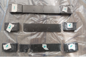
The images of the specimens after the tensile test are shown in Figures 10-13.
As can be understood from the images after the experiment, fracture perpendicular to the fiber direction occurred in the specimens taken at 0° and 45° and produced by compression molding. This situation could not be observed in the 90° specimens because of slipping in the grips of the universal testing machine; however, when the maximum stress, elongation, and elastic moduli observed in the simulations are examined, it can be concluded that, due to the symmetry of the material, fracture should occur in the same way as in the specimens with 0° fiber orientation. In the specimens with 0° fiber orientation produced by the pultrusion method, fracture did not occur completely in the experiment because of cracks formed in the fiber direction. This situation is due to the presence of multiple factors affecting the experimental conditions. It was concluded that, under normal conditions, the tensile test data should be close to the data obtained from the analysis.
The experiments and analyses showed that different fiber orientations and the materials used directly affect the mechanical properties and behavior of composites under tensile load. The results show that the composite material produced by 0° pultrusion is the material most resistant to stress and that, because its strain is lower than that of the specimens produced by compression molding, it exhibits a stiffer and more brittle structure.
The graphs and tables contain the database data to be created for the materials.
Figure 10. 0° Compression Molding, Images of the Specimens After the Test.0° Compression Molding, Images of the Specimens After the Test.
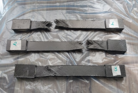
Figure 11. 45° Compression Molding, Images of the Specimens After the Test.45° Compression Molding, Images of the Specimens After the Test.
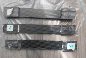
Figure 12. 90° Compression Molding, Images of the Specimens After the Test.90° Compression Molding, Images of the Specimens After the Test.
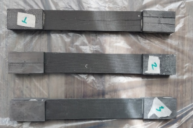
Figure 13. 0° Pultrusion, Images of the Specimens After the Test. 0° Pultrusion, Images of the Specimens After the Test.
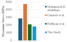
In the studies conducted in the literature, Mohammed and Abdelbary performed tensile tests on unidirectional carbon fiber-based epoxy composites with fiber orientations of 0°, 30°, 45°, 60°, and 90°. The tensile stresses of the composites were reported as 2857 MPa for 0°, 99 MPa for 45°, and 58 MPa for 90°, while the tensile strains were given as 4% for 0°, 7.1% for 45°, and 1.9% for 90°. The elastic modulus were reported as 127.54 GPa for 0°, 2.5 GPa for 45°, and 5.8 GPa for 90°. When compared with the studies conducted using pultrusion, it is observed that the tensile stresses gave accurate results in both the experiments and analyses, while the elastic modulus of the composite with 45° fiber orientation was higher than in our study because the strain value obtained from the analysis was considerably low. This difference may have resulted from incomplete or incorrect analysis of the parameters selected during the analysis.
In another study, Canaroli et al. performed tensile tests on unidirectional prepreg, plain-woven, and twill-woven carbon fiber-based polymer composites. The maximum stress, strain, and elastic modulus of the unidirectional composite were reported as 4734 MPa, 2.01%, and 235 GPa, respectively. For the composites produced from plain-woven fabric, the maximum stress, strain, and elastic modulus were reported as 530 MPa, 1.31%, and 38 GPa, respectively. In the findings, it was stated that the 0° orientation dominated the tensile performance. It was also indicated that strength and stiffness were at the highest level in unidirectional composites. The findings support the experimental and analytical results.
Hoffman et al. conducted tests to examine the mechanical properties of unidirectional carbon fiber-reinforced composites produced by the pultrusion method. This composite, consisting of a bio-based unsaturated polyester matrix, reached tensile strength, strain, and elastic modulus values of 2095 MPa, 1.4%, and 167 GPa, respectively. It is observed that the experimental and analytical results obtained for the composites with 0° fiber orientation produced by the pultrusion method in this study are close to those reported in the literature.
Figures 14-16 show the comparison of the experimental data of the unidirectional composites with 0° fiber orientation obtained in this study with the studies reported in the literature.
Figure 14. Comparison of the Experimental Data of Unidirectional Composites with 0° Fiber Orientation with Studies in the Literature (Maximum Stress).Comparison of the Experimental Data of Unidirectional Composites with 0° Fiber Orientation with Studies in the Literature (Maximum Stress).
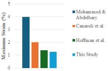
Figure 15. Comparison of the Experimental Data of Unidirectional Composites with 0° Fiber Orientation with Studies in the Literature (Maximum Strain).Comparison of the Experimental Data of Unidirectional Composites with 0° Fiber Orientation with Studies in the Literature (Maximum Strain).
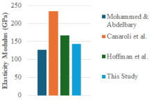
Figure 16. Comparison of the Experimental Data of Unidirectional Composites with 0° Fiber Orientation with Studies in the Literature (Elasticity Modulus).Comparison of the Experimental Data of Unidirectional Composites with 0° Fiber Orientation with Studies in the Literature (Elasticity Modulus).

4. Conclusion
In this study, the mechanical properties of carbon fiber-based composite materials were determined through experiments and simulations. The production methods, materials, and fiber orientations of the composites used in the determinations were taken into account. Tensile tests on two different composites consisting of plain and unidirectional fabrics produced by compression molding and pultrusion were performed using a Universal Testing Machine (Zwick) (UTM-ZW) and Finite Element Analyses (FEA) were made in the ABAQUS CAE program in a computer environment. The following conclusions summarize the findings.
1) It was found that material changes arising from the production methods used to determine the mechanical properties of the composites and the behavior of the material at different fiber orientations are influential factors. The effects of these factors on tensile properties were examined both in the experiment and in the simulation.
2) Results that are close to and acceptable compared with the data obtained from the experiments can be found by Finite Element Analyses in a more practical, faster, and cost-free manner. In addition, the factors affecting the experimental results cease to be influential elements in these analyses.
3) In the tests performed in the 0° fiber layup direction, it was concluded that the composite produced by the pultrusion method was more rigid (stiffer) than the composite produced by the compression method, underwent less deformation under the same stress, and was more resistant to elastic deformation.
4) Placement of the carbon fibers of the composite material in the 0° direction provided superior mechanical properties compared with the other orientations.
5) The database data to be created for the composites used in the compression molding and pultrusion methods were given in the tables and graphs.
Abbreviations

FEA

Finite Element Analysis

ISO

International Organization for Standardization

CAE

Computer-aided Engineering

PAN

Polyacrylonitrile

UTM-ZW

Universal Testing Machine (Zwick)

Author Contributions
Anil Furkan Yavuz: Conceptualization, Data curation, Formal Analysis, Investigation, Methodology, Project administration, Software, Validation, Visualization, Writing – original draft, Writing – review & editing
Zafer Tekiner: Conceptualization, Resources, Supervision, Validation, Writing – review & editing
Conflicts of Interest
The authors declare no conflicts of interest.
References
[1] Tanaka, F. Pioneering the carbon fiber frontier: A half-century of industry leadership and the road ahead, Composites Part B: Engineering, 2024, 281, 111515.
[2] Lu, Z. Review on the precursor preparation and carbon fiber manufacturing, Journal of Physics: Conference Series, 2021, 1798(1), 012003.
[3] Zhao, X., Lu, X., Tze, W. T. Y., Wang, P. A single carbon fiber microelectrode with branching carbon nanotubes for bioelectrochemical processes, Biosensors and Bioelectronics, 2010, 25(10), 2343–2350.
[4] Advani, S. G., Sozer, E. M. Introduction. In Process Modeling in Composites Manufacturing, 1st ed, Marcel Dekker, 2003, pp. 12-32.
[5] Krzyzak, A., Mazur, M., Gajewski, M., Drozd, K., Komorek, A., Przybyłek, P. Sandwich structured composites for aeronautics: methods of manufacturing affecting some mechanical properties, International Journal of Aerospace Engineering, 2016, 2016(1), 7816912.
[6] Phunpeng, V., Boransan, W., Horpibulsuk, S. Comprehensive Analysis of In-Plane Tensile Characteristics of Hybrid Composite Using Finite Element Method, Journal of Engineering Research, 2025, 13(2), 1294–1306.
[7] Monti, M., Palenzona, M., Fiorino, F., Baudach, F., Onnis, A., Romeo, A. Design, manufacturing and FEA prediction of the mechanical behavior of a hybrid-molded polycarbonate / continuous carbon fiber reinforced composite component, Composites Part B: Engineering, 2022, 238, 109891.
[8] Galati, M., Viccica, M., Minetola, P. A finite element approach for the prediction of the mechanical behaviour of layered composites produced by continuous filament fabrication (CFF), Polymer Testing, 2021, 98, 107181.
[9] Ansari, M. N. M., Vinoth, K. S., Nordin, A., Bassam, A., Topa, A. Tensile properties of hybrid kenaf/glass fiber reinforced epoxy composites with different stacking sequence using experimental and FEA simulation method, IOP Conference Series: Materials Science and Engineering, 2021, 1128(1), 012023.
[10] Noman, A. A., Shohel, S. M., Riyad, S. H., Gupta, S. S. Investigate the mechanical strength of laminated composite carbon fiber with different fiber orientations by numerically using finite element analysis, Materials Today: Proceedings, 2023.
[11] Ikbal, M. H., Ahmed, A., Qingtao, W., Shuai, Z., Wei, L. Hybrid composites made of unidirectional T600S carbon and E-glass fabrics under quasi-static loading, Journal of Industrial Textiles, 2017, 46(7), 1511–1535.
[12] Dwivedi, V., Mandla, P., Gupta, D., Chandel, R., Sharma, A. Simulation of tensile behaviour of carbon fiber reinforced polymer matrix composite, Materials Today: Proceedings, 2023.
[13] Mohamed, Y. S., Abdelbary, A. Theoretical and experimental study on the influence of fiber orientation on the tensile properties of unidirectional carbon fiber/epoxy composite, Alexandria Engineering Journal, 2023, 67, 693–705.
[14] Canaroli, L., Baldi, N., Del Pero, F., La Battaglia, V., Arcidiacono, G., Citti, P. Mechanical characterization of carbon fiber composite materials with different reinforcement and thickness cured in autoclave, Hybrid Advances, 2025, 11, 100550.
[15] Hofmann, M., Machado, M., Shahid, A. T., Dourado, F., Garrido, M., Bordado, J. C., Correia, J. R. Pultruded carbon fibre reinforced polymer strips produced with a novel bio-based thermoset polyester for structural strengthening, Composites Science and Technology, 2023, 234, 109936.
Cite This Article
  • APA Style

    Yavuz, A. F., Tekiner, Z. (2026). Production of Carbon Fiber Reinforced Composites and Determination of Their Mechanical Properties. International Journal of Industrial and Manufacturing Systems Engineering, 11(2), 24-34. https://doi.org/10.11648/j.ijimse.20261102.11

    Copy | Download

    ACS Style

    Yavuz, A. F.; Tekiner, Z. Production of Carbon Fiber Reinforced Composites and Determination of Their Mechanical Properties. Int. J. Ind. Manuf. Syst. Eng. 2026, 11(2), 24-34. doi: 10.11648/j.ijimse.20261102.11

    Copy | Download

    AMA Style

    Yavuz AF, Tekiner Z. Production of Carbon Fiber Reinforced Composites and Determination of Their Mechanical Properties. Int J Ind Manuf Syst Eng. 2026;11(2):24-34. doi: 10.11648/j.ijimse.20261102.11

    Copy | Download

  • @article{10.11648/j.ijimse.20261102.11,
      author = {Anil Furkan Yavuz and Zafer Tekiner},
      title = {Production of Carbon Fiber Reinforced Composites and Determination of Their Mechanical Properties},
      journal = {International Journal of Industrial and Manufacturing Systems Engineering},
      volume = {11},
      number = {2},
      pages = {24-34},
      doi = {10.11648/j.ijimse.20261102.11},
      url = {https://doi.org/10.11648/j.ijimse.20261102.11},
      eprint = {https://article.sciencepublishinggroup.com/pdf/10.11648.j.ijimse.20261102.11},
      abstract = {In this study, tensile tests of carbon fiber-based composite materials produced by compression molding and pultrusion were conducted at 0°, 45°, and 90° fiber orientations through experiments and Finite Element Analyses (FEA), and database data were obtained for the materials. In the study, plain-weave prepreg composites were used in the compression molding method, while carbon fiber yarns were used in the pultrusion method. Tensile tests were carried out on a universal testing machine in accordance with the ISO 527-4 standard. The experimental data obtained were compared with Finite Element Analyses performed in the ABAQUS CAE environment. The results showed that fiber orientation has a decisive effect on the mechanical properties of composites. It was determined that specimens taken in the 0° fiber orientation exhibited superior mechanical properties compared with specimens in the other orientations. It was observed that composites with 0° fiber orientation produced by the pultrusion method showed higher stiffness, underwent lower deformation under the same stress, and were more resistant to elastic deformation. It was evaluated that there was general agreement between the experimental results and numerical analyses, while the observed differences were caused by factors such as production-related defects, test conditions, and the ideal assumptions used in the simulations. The findings reveal that the production method and fiber layup angle are critical parameters in optimizing the mechanical properties of carbon fiber composites.},
     year = {2026}
    }
    

    Copy | Download

  • TY  - JOUR
    T1  - Production of Carbon Fiber Reinforced Composites and Determination of Their Mechanical Properties
    AU  - Anil Furkan Yavuz
    AU  - Zafer Tekiner
    Y1  - 2026/11/06
    PY  - 2026
    N1  - https://doi.org/10.11648/j.ijimse.20261102.11
    DO  - 10.11648/j.ijimse.20261102.11
    T2  - International Journal of Industrial and Manufacturing Systems Engineering
    JF  - International Journal of Industrial and Manufacturing Systems Engineering
    JO  - International Journal of Industrial and Manufacturing Systems Engineering
    SP  - 24
    EP  - 34
    PB  - Science Publishing Group
    SN  - 2575-3142
    UR  - https://doi.org/10.11648/j.ijimse.20261102.11
    AB  - In this study, tensile tests of carbon fiber-based composite materials produced by compression molding and pultrusion were conducted at 0°, 45°, and 90° fiber orientations through experiments and Finite Element Analyses (FEA), and database data were obtained for the materials. In the study, plain-weave prepreg composites were used in the compression molding method, while carbon fiber yarns were used in the pultrusion method. Tensile tests were carried out on a universal testing machine in accordance with the ISO 527-4 standard. The experimental data obtained were compared with Finite Element Analyses performed in the ABAQUS CAE environment. The results showed that fiber orientation has a decisive effect on the mechanical properties of composites. It was determined that specimens taken in the 0° fiber orientation exhibited superior mechanical properties compared with specimens in the other orientations. It was observed that composites with 0° fiber orientation produced by the pultrusion method showed higher stiffness, underwent lower deformation under the same stress, and were more resistant to elastic deformation. It was evaluated that there was general agreement between the experimental results and numerical analyses, while the observed differences were caused by factors such as production-related defects, test conditions, and the ideal assumptions used in the simulations. The findings reveal that the production method and fiber layup angle are critical parameters in optimizing the mechanical properties of carbon fiber composites.
    VL  - 11
    IS  - 2
    ER  - 

    Copy | Download

Author Information