1. Introduction
Cylindrical hydraulic dampers have been widely used as shock energy absorption components to mitigate vibration damage caused by events such as earthquakes and collisions, and many studies have been published on their damping performance against impact vibrations
| [1] | Paswan, R., Das, J., Kumar, N., Kumar, A., Mishra S. K., & Kumar, S., (2014) Hydraulic circuit in damper: an overview. Applied Mechanics and Materials, 592-594, 2056-2060. https://doi.org/10.4028/www.scientific.net/AMM.592-594.2056 |
| [2] | Wu, Z., Xu, G., Yang, H., & Li, M., (2021). Analysis of Damping Characteristics of a Hydraulic Shock Absorber. Shock and Vibration, 2021, 8883024. https://doi.org/10.1155/2021/8883024 |
| [3] | Czop, P., Sławik, D., & Wszołek, G., (2013). Development of an optimization method for minimizing vibrations of a hydraulic damper. Simulation, 89(9), 1073-1086. https://doi.org/10.1177/0037549713486012 |
| [4] | Sun, J., Jiao, S., Huang, X., & Hua, H., (2014). Investigation into the Impact and Buffering Characteristics of a Non-Newtonian Fluid Damper: Experiment and Simulation. Shock and Vibration, 2014, 170464. https://doi.org/10.1155/2014/170464 |
| [5] | Gao, H., Chi, M., Dai, L., Yang, J., & Zhou, X., (2020). Mathematical Modelling and Computational Simulation of the Hydraulic Damper during the Orifice-Working Stage for Railway Vehicles. Mathematical Problems in Engineering, 2020, 1830150. https://doi.org/10.1155/2020/1830150 |
| [6] | Jugulkar, L. M., Singh, S., & Sawant, S. M., (2016). Fluid flow modeling and experimental investigation on automobile damper. Construction and Building Materials, 121, 760-772. https://doi.org/10.1016/j.conbuildmat.2016.05.142 |
[1-6]
.
To effectively absorb impact forces such as those experienced by automobiles traveling on complex roads or during vehicle collisions, researchers have conducted studies on applying hydraulic dampers to suspensions and other systems to improve ride comfort and occupant safety as much as possible
| [7] | Ahmed, M. R. Yusoff, A. R. & Romlay, F. R. M., (2019). Numerical Investigation of Continuous Damping of The SemiActive Suspension System for Passenger Car. IOP Conf. Series: Materials Science and Engineering, 530, 012014. https://doi.10.1088/1757-899X/530/1/012014 |
| [8] | Dobre, A., (2021). Modelling the dynamic behaviour of car hydraulic dampers. IOP Conf. Series: Materials Science and Engineering, 1091, 012018. https://doi.10.1088/1757-899X/1091/1/012018 |
| [9] | Dharankar, C. S., Hada, M. K., & Chandel, S., (2019). Experimental identification of non-hysteresis algebraic force model of automotive hydraulic damper. International Journal of Vehicle Performance, 5(2), 213-231. https://doi.org/10.1504/IJVP.2019.098999 |
| [10] | Azimi, M., Rasoulnia, A., Liu, Z., & Pan, H., (2017). Improved semi-active control algorithm for hydraulic damper-based braced buildings. Structure Control Health Monitor, 24, 11. https://doi.org/10.1002/stc.1991 |
[7-10]
. Efforts have also been made to improve the damping performance of railway vehicles traveling at high speeds on Shinkansen rails to reduce vibrations and enhance running stability
| [11] | Huang, C., & Zeng, J., (2018). Dynamic behaviour of a high-speed train hydraulic yaw damper. Vehicle System Dynamics, 56, 12. https://doi.org/10.1080/00423114.2018.1439588 |
| [12] | Wang, W., Liang, Y., Zhang, W., & Iwnicki, S., (2019). Effect of the nonlinear displacement-dependent characteristics of a hydraulic damper on high-speed rail pantograph dynamics. Nonlinear Dynamics, 95, 3439-3464. https://doi.org/10.1007/s11071-019-04766-4 |
[11, 12]
. For earthquake-induced damage to high-rise buildings and residential structures to be mitigated, research has been conducted on installing cylindrical hydraulic dampers along the diagonal directions of rectangular frame structures, utilizing their damping and vibration control capabilities
| [13] | Go, C., Sui, C., Shih, M., & Sung, W., (2010). A Linearization Model for the Displacement Dependent Semi-active Hydraulic Damper. Journal of Vibration and Control, 16(14), 2195-2214. https://doi.org/10.1177/1077546309349433 |
| [14] | Shin, M., Lin, C., & Sung, W., (2013). Numerical Analysis for Shock Absorption Performance of Accumulated Semi-Active Hydraulic Damper. Journal of Dynamical Systems and Geometric Theories, 4(1), 29-45. https://doi.org/10.1080/1726037X.2006.10698501 |
| [15] | Goldasz, J., Sapinski, B., Jastrzebski, L., & Kubik, M., (2020). Dual Hysteresis Model of MR Dampers. Frontiers in Materials, 7, 236. https://doi.org/10.3389/fmats.2020.00236 |
[13-15]
. Additionally, for active control functionality in hydraulic dampers, studies have been conducted in which magnetic fields were externally applied to conventional hydraulic dampers to modify their damping characteristics, and numerous research results have been published in this area
| [16] | Raut, L. B., Khedkar, Y. M., Salunke, S. Y., & Jadhav, S. V., (2019). Modification of Classical Hydraulic damper into Semi active damper using MR Approach. International Journal of Scientific and Research Publications, 9(3), 676-683. http://dx.doi.org/10.29322/IJSRP.9.03.2019.p8795 |
| [17] | Hu, K., Li, F., Zhang, Z., Wang, S., & Jiang, H., (2021). A Magnetoelectric Hybrid Hydraulic Damper for the Mining Robot Suspension System. Shock and Vibration, 2021, 5479423. https://doi.org/10.1155/2021/5479423 |
| [18] | Sharma, S. V., & Hemalatha, G., (2022). Numerical and Experimental Investigation on Small Scale Magnetorheological Damper. International Journal of Engineering, 35(12), 2395-2402. https://doi.org/10.5829/ije.2022.35.12c.16 |
| [19] | Sharma, S. V., & Hemalatha, G., (2023). Small-scale MR damper: design, fabrication and evaluation. Asian Journal of Civil Engineering, 24, 1489-1499. https://doi.org/10.1007/s42107-023-00582-9 |
| [20] | Guan, J., Zheng, B., Li, Y, Zhao, W., & Zhao, X., (2024). Research on Bifurcated Origami Hydraulic Dampers for Real Road Vibration Loads. Applied Sciences, 14, 6374. https://doi.org/10.3390/app14146374 |
[16-20]
.
However, most existing hydraulic dampers are fabricated from metal cylinders, and the actual length available for axial extension and contraction is limited relative to the total length, making them difficult to use in applications with restricted installation space. Furthermore, for weight reduction, the demand for the development of new types of hydraulic dampers created from lightweight nonmetallic materials as alternatives to conventional metal cylindrical dampers in increasing.
Therefore, the geometric configuration of tubular origami structures, which can be freely folded along the axial direction, has attracted interest, and the application of origami structures to hydraulic dampers as an alternative to conventional metal cylindrical dampers has been proposed
| [21] | Huang, Z., Wei, C., Dong, L., Wang, A., Yao, H., Guo, Z., & Mi, S., (2022). Fluid-driven hydrogel actuators with an origami structure. iScience, 25(7), 104674. https://doi.org/10.1016/j.isci.2022.104674 |
| [22] | Ye, S., Zhao, P., Zhao, Y., Kavousi, F., Feng, H., & Hao, G., (2022). A Novel Radially Closable Tubular Origami Structure (RC-ori) for Valves. Actuators, 11, 243. https://doi.org/10.3390/act11090243 |
| [23] | Lebee, A., (2015). From Folds to Structures: a Review. International Journal of Space Structures, 30(2), 55-74. https://doi.org/10.1260/0266-3511.30.2.55 |
[21-23]
. Fundamental studies have been conducted on origami structures from geometric and other basic perspectives to achieve practical applications of origami hydraulic dampers
| [24] | Dureisseix, D., (2012). An Overview of Mechanisms and Patterns with Origami. International Journal of Space Structures, 27, 1. https://doi.org/10.1260/0266-3511.27.1.1 |
| [25] | Shen, T., & Nagai, Y., (2017). An Overview of Folding Techniques in Architecture Design. World Journal of Engineering and Technology, 5, 12-19. https://doi.org/10.4236/wjet.2017.53B002 |
| [26] | Reid, A., Lechenault, F., Rica, S., & Bedia, M. A., (2017). Geometry and design of origami bellows with tunable response. Physical Review E, 95, 013002. https://doi.org/10.1103/PhysRevE.95.013002 |
| [27] | Lv, C., Krishnaraju, D., Konjevod, G., Yu, H., & Jiang, H., (2014). Origami based Mechanical Metamaterials, Scientific Reports. 4, 5979. https://doi.org/10.1038/srep05979 |
| [28] | Guest, S., & Pellegrino, S., (1994). The Folding of Triangulated Cylinders, Part I: Geometric Considerations. Journal of Applied Mechanics, 61(4), 773-777. https://doi.org/10.1115/1.2901553 |
| [29] | Shen, W., Cao, Y., Jiang, X., Zhang, Z., Kremer, G. E. Q., & Qin, H., (2022). Experimental and Numerical Investigation on Radial Stiffness of Origami-Inspired Tubular Structures. Journal of Applied Mechanics, 89(3), 031001. https://doi.org/10.1115/1.4052799 |
[24-29]
. Furthermore, the deformation characteristics of tubular origami structures subjected to external forces along the axial direction have been investigated
| [30] | Terada, K., Kadoi, K., Tokura, S., Sushida, T., & Hagiwara, I., (2017). The deformation mechanism on origami-based foldable structures. International Journal of Vehicle Performance, 3(4), 334-346. https://doi.org/10.1504/IJVP.2017.086911 |
| [31] | Agarwal, V., & Wang, K., (2022). On the nonlinear dynamics of a Kresling-pattern origami under harmonic force excitation. Extreme Mechanics Letters, 52, 101653. https://doi.org/10.1016/j.eml.2022.101653 |
| [32] | Yue, W., Qi, J., Song, X., Fan, S., Fortino, G., Chen. C., Xu, C., & Ren, H., (2022). Origami-Inspired Structure with Pneumatic-Induced Variable Stiffness for Multi-DOF Force-Sensing. Sensors, 22(14), 5370. https://doi.org/10.3390/s22145370 |
| [33] | Hu, Y., Zhou, Y., Kwok, K., & Sze, K. Y., (2021). Simulating flexible origami structures by finite element method. International Journal of Mechanics and Materials in Design, 17, 801-829. https://doi.org/10.1007/s10999-021-09538-w |
[30-33]
.
However, existing origami hydraulic dampers require a connection to an external hydraulic oil tank via linking pipes
| [34] | Guan, J., Zuo, J., Zhao, W., Gomi, N., & Zhao, X., (2022). Study on Hydraulic Dampers Using a Foldable Inverted Spiral Origami Structure. Vibration, 5, 711-731. https://doi.org/10.3390/vibration5040042 |
[34]
, and no notable research has applied this concept directly to origami hydraulic dampers. Therefore, lightweight origami hydraulic dampers that can be installed in limited spaces must be developed.
In this paper, a novel internal-flow origami hydraulic damper is proposed. First, the structure of this damper is examined, and a formula is derived to calculate the motion damping force generated by the internal fluid flow. To verify the damping characteristics of the proposed damper, we developed a validation experimental system using an origami hydraulic damper in a mass-spring vibration system, and shaking tests were conducted using actual earthquake waves. For further investigation, shaking experiments were performed by varying the diameter of the damping holes located at the origami structure and by changing the internal fluid. The damping effectiveness and practical applicability of the proposed internal-flow origami hydraulic damper were evaluated by comparing the measured response acceleration values of the vibrating body.
2. Materials and Methods
2.1. Internal-flow Origami Hydraulic Damper
As shown in
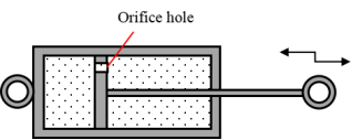
Figure 1, a conventional cylindrical hydraulic damper consists of a sealed cylindrical body divided into two hydraulic chambers by a piston that moves in the axial direction. The piston is equipped with orifice holes; as it moves axially, the internal fluid flows through these orifices, generating a damping force acting on the piston. Moreover, the magnitude of the damping force can be adjusted by changing the orifice hole size.
However, cylindrical hydraulic dampers have two major limitations. First, the effective damping length available for use as a damper is limited to less than half the maximum stroke length of the piston. Second, when the piston is subjected to not only axial motion but also lateral external loads or disturbances, cylindrical hydraulic dampers become difficult to apply, and problems such as wear of the piston seals occur. A method of connecting the damper at both ends using rotary joints, as shown in
Figure 1, can be employed to address this; however, this introduces a stress concentration localized at the rotary joints. Moreover, even with rotary joints, the problem of coping with external loads in an indeterminate direction remains unresolved.
Figure 1. Conventional cylindrical hydraulic damper.
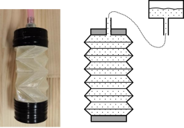
Therefore, the authors proposed an externally connected origami hydraulic damper, as shown in
Figure 2, and the experimental results from the actual vibration tests confirmed that the two major limitations of the cylindrical hydraulic damper can be improved
| [34] | Guan, J., Zuo, J., Zhao, W., Gomi, N., & Zhao, X., (2022). Study on Hydraulic Dampers Using a Foldable Inverted Spiral Origami Structure. Vibration, 5, 711-731. https://doi.org/10.3390/vibration5040042 |
[34]
. However, as shown in
Figure 2, the externally connected origami hydraulic damper requires linking pipes to connect the origami damper to an external fluid tank. This presents a challenge for practical implementation that is yet to be resolved.
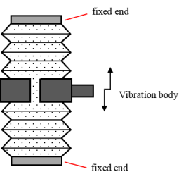
In this paper, an internal-flow origami hydraulic damper is proposed. As shown in
Figure 3, the external hydraulic oil tank is omitted. The origami hydraulic damper is fixed at both end faces using plate components and a mass block connected to an external vibrating body is attached at the center. An orifice hole is drilled at the center of the mass block.
Figure 3. Internal-flow origami hydraulic damper.
In actual use, the mass block moves axially with the external vibrating body, and the internal fluid flows through the orifice hole in the mass block, generating a damping force acting on the mass block.
2.2. Damping Force of Origami Hydraulic Damper
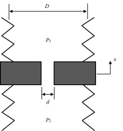
For analysis, a portion of the internal-flow origami hydraulic damper shown in
Figure 3 is extracted to create the analytical model depicted in
Figure 4. Here, D denotes the average diameter of the origami hydraulic damper, and d represents the diameter of the orifice hole. P₁ and P₂ are the fluid pressures on both sides of the mass block, respectively.
Figure 4. Analytical model of an internal-flow origami hydraulic damper.
The flow volume of the fluid inside the origami hydraulic damper passing through the orifice hole can be calculated using the following equation
| [35] | Cengel, Y. A., & Cimbala, J. M., (2006). Fluid Mechanics: Fundamentals and Applications. McGraw-Hill. |
[35]
:
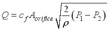 (1)
(1) Here,
cf is the flow coefficient, which is affected by the viscosity of the liquid. In this study, we set
cf = 0.61 based on the measurement experimental formula in Referent
| [35] | Cengel, Y. A., & Cimbala, J. M., (2006). Fluid Mechanics: Fundamentals and Applications. McGraw-Hill. |
[35]
.
Aorifice is the cross-sectional area of the orifice hole, and

is water density. Moreover, the flow volume of the fluid passing through the origami structure section can be calculated using the following equation.
 (2)
(2) Here,
Aorigami is the cross-sectional area of the origami structure, and

is the velocity of the mass block. The following equation can be derived from the condition that the internal flow volume of the origami hydraulic damper remains constant throughout.
 (3)
(3) By rearranging Equation (
3), the following expression is obtained:
 (4)
(4) The pressure loss and cross-sectional area are expressed as follows:
 (5)
(5)  (6)
(6)  (7)
(7) By substituting Equations (
5) - (
7) into Equation (
4), the following equation is obtained:
 (8)
(8) The damping force generated when the origami hydraulic damper is used can be calculated as the product of the pressure difference between the internal fluid and the ring-shaped cross-sectional area of the mass block, as shown in the following equation:
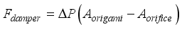 (9)
(9) By substituting Equations (
6) - (
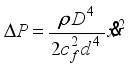
8), the following formula for calculating the damping force of the origami hydraulic damper is obtained:
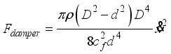 (10)
(10) The damping coefficient of the origami hydraulic damper is expressed as follows:
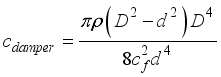 (11)
(11) According to Equation (
11), the damping coefficient of the origami hydraulic damper is determined by the geometric parameters that constitute the damper, orifice hole, and internal fluid type. Using Equation (
11), the damping force of the origami hydraulic damper can be calculated as follows:
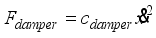 (12)
(12) Equation (
12) shows that the damping force of the origami hydraulic damper is proportional to the square of the mass block velocity.
As an example of the origami hydraulic damper configuration, the average diameter of the origami structural part is
D=45mm, the diameter of the orifice hole is
d=30mm, the flow coefficient is
cf =0.61, and water is used as the internal fluid with a density of

=1000 kg/m
3. Substituting these values into Equation (
11), the damping coefficient can be obtained as follows:
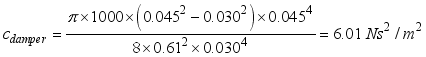 (13)
(13) With the calculation results from Equation (
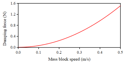
13), the relationship between the damping force of the origami hydraulic damper and velocity of the mass block is shown in
Figure 5.
Figure 5. Relationship between damping force and motion speed of the origami hydraulic damper.
Figure 5 shows that when the velocity of the mass block is low, the damping force is relatively low. However, as the velocity of the mass block increases, the damping force tends to increase rapidly in proportion to the square of the velocity. This nonlinear damping characteristic was confirmed to differ from typical viscous damping caused by friction.
2.3. Fabricate an Origami Hydraulic Damper
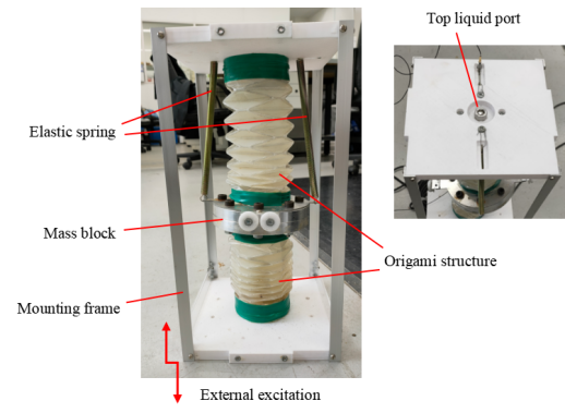
To verify the damping characteristics of the internal-flow origami hydraulic damper proposed and examined in the previous section, we developed an experimental setup, as shown in
Figure 6. The experimental setup primarily consisted of a frame structure and an origami hydraulic damper set.
Because the origami hydraulic damper does not return to its original position after external vibration excitation, an elastic spring must be attached to the mass block of the origami hydraulic damper and used together.
As shown in
Figure 6, the origami hydraulic damper set was installed at the center of a frame structure composed of two flat plates (one on the top and one at the bottom) and four angle steel columns. The end faces of the origami hydraulic dampers were fixed to the top and bottom plates of the frame. The mass block at the center of the origami hydraulic damper was suspended using two elastic springs and attached to the underside of the upper part of the frame. The right side of
Figure 6 shows the liquid injection port installed on the top surface of the frame.
For verification, the setup shown in
Figure 6 was mounted on a vibration table. When the vibration table applied excitation along the vertical direction, the mass block moved relative to the frame structure.
Figure 6. Verification test device for the origami hydraulic damper.
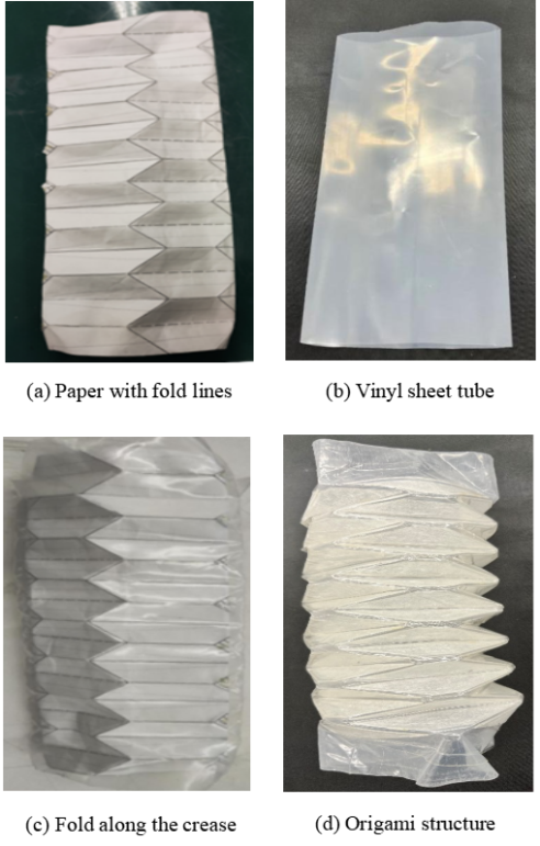
Origami structural components can be fabricated using the procedure shown in
Figure 7. As shown in
Figure 7(a), a development drawing of the origami structure designed using a CAD (Computer Aided Design) system was printed and folded along the crease lines. Next, as shown in
Figure 7(b), a cylindrical vinyl sheet tube was prepared and paper with printed crease lines was inserted inside it. As shown in
Figure 7(c), the vinyl sheet tube was folded carefully along the crease lines of the paper, and the outside was wrapped with two to three layers of adhesive tape. Consequently, the origami structural component shown in
Figure 7(d) was obtained.
Figure 7. Fabrication of the origami structural parts in this study.
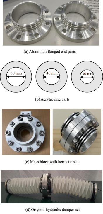
Figure 8. Fabrication process for the mass block and the origami hydraulic damper set.
Figure 8 shows the fabrication process for the mass block and the origami hydraulic damper set.
First, as shown in
Figure 8(a), an aluminum end part with a flange was machined, and a groove was cut into the shaft portion to attach a sealing ring.
Next, to control the magnitude of the damping force of the origami hydraulic damper, we fabricated ring parts from thin acrylic plates, as shown in
Figure 8(b), with central hole diameters of the three rings being 30, 40, and 50mm, respectively. During the vibration verification experiments, the damping force of the origami hydraulic damper was adjusted by replacing these rings with those of different diameters.
Furthermore, the rings were sandwiched between the two flange end parts, and, as shown in
Figure 8(c), bolts were inserted through the holes along the circumference and tightened securely, completing the fabrication of the mass block.
Finally, the sealing rings and origami structural parts were attached to both sides of the mass block, resulting in the origami hydraulic damper set shown in
Figure 8(d).
Figure 9. Verification test system and measurement flow chart.
Figure 10. Verification test device for the internal-flow origami hydraulic damper.
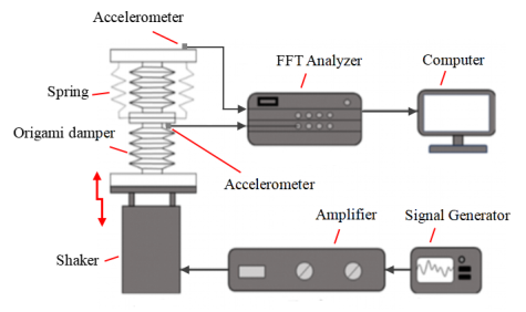
The experimental verification system shown in
Figure 9 consists of a vibration table, an amplifier, a signal generator, acceleration sensors, a fast FFT (Fast Fourier transform) analyzer, and a computer for data processing.
The measurement procedure was performed according to the flowchart shown in
Figure 9. First, the signal generator produced a vibration input signal and sent it to the amplifier. The amplified vibration signal was then sent to the vibration table, which excited the vibration model of the origami hydraulic damper fixed on it. Acceleration sensors detect the response acceleration signals from both the frame and mass block, which were recorded by the FFT analyzer. Finally, the measured vibration response data were processed and output using the computer.
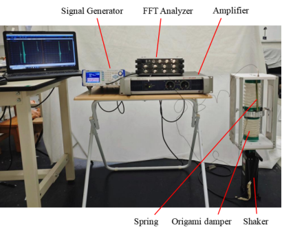
Figure 10 shows the experimental setup to verify the fabricated internal-flow origami hydraulic damper.
2.4. Experimental Earthquake Excitation Signal
The excitation vibration waveforms used in the verification experiments in this study were actual measured seismic acceleration waves.
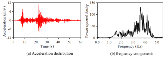
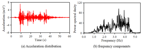
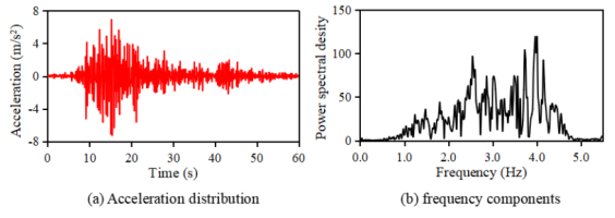
Figures 11, 12, 13 show the Fukushima, El Centro NS, and Taft NW earthquake waves, respectively, along with the frequency components obtained by performing a Fourier transform.
Figure 11. Fukushima earthquake excitation signal.
Figure 12. EI Centro NS earthquake excitation signal.
Figure 13. Taft NW earthquake excitation signal.
The earthquake waves shown in
Figures 11 - 13 were concentrated in the main frequency range of 2.0 - 5.0 Hz and exhibited overall characteristics of random excitation performance.
2.5. Evaluation Value of Response Acceleration Due to Earthquakes
The response acceleration results obtained from the earthquake excitation were randomly distributed, making a direct comparison of different response acceleration results difficult.
To quantitatively evaluate the random response vibration characteristics, we used the standard deviation S of the response acceleration, defined by the following equation, as the evaluation criterion:
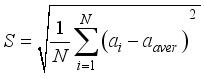 (14)
(14) where ai is the measured value of the vibration-response acceleration, aaver is the average of the measured ai values, and N is the number of measurement samples in the experiment.
Furthermore, the vibration control effect of the Origami hydraulic damper is evaluated using the reduction ratio RS defined by the following equation.
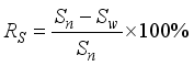 (15)
(15) Here, Rn is the standard deviation of the response acceleration when there is no water in the origami damper, and Rw is the standard deviation of the response acceleration when there is water in the origami damper.
3. Results and Discussion
To verify the damping effect of the origami hydraulic damper, we conducted vibration experiments using actual earthquake waves with and without the origami damper filled with water. The measured response accelerations of the mass blocks were compared and analyzed for each case.
Here, we assumed that the origami structure was completely folded along the crease lines and offered a sufficiently small resistance to compressive deformation along the axial direction of the origami structure. For convenience in the measurement experiments, the response acceleration values measured without water in the origami structure were used as the baseline for comparison and evaluation.
3.1. Verification of Vibration Control Effect
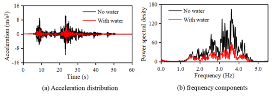
Figure 14 shows the measured response acceleration results for the origami hydraulic damper with an orifice hole diameter of 40mm subjected to vibration caused by the Fukushima earthquake wave.
In
Figure 14, the black solid line represents the response acceleration measurements when the origami structure was not filled with water, whereas the red dotted line represents the response acceleration measurements when the origami structure was filled with water.
Figure 14. Measurement experiment results (Fukushima earthquake, orifice diameter 40mm).
As shown in the comparison results of the response acceleration in
Figure 14(a), the amplitude of the response acceleration was clearly smaller for the origami hydraulic damper filled with water than that without water. The standard deviation of the response acceleration for the origami hydraulic damper without water was 1.67m/s², whereas that for the damper filled with water was 0.61m/s², confirming a significant reduction of approximately 63.49%.
As shown in the comparison of frequency components of the response acceleration in
Figure 14(b), across the main frequency range of 1.0-5.0 Hz, the frequency response values of the damper filled with water were consistently lower than those without water. This indicated that the proposed origami hydraulic damper has excellent damping and vibration suppression characteristics.
3.2. Effects of Orifice Hole Diameter
The size of the orifice hole through which water passes in the origami hydraulic damper is considered to have a significant impact on its damping performance.
For the investigation, maintaining the excitation conditions described in the previous section with the Fukushima earthquake wave; only the diameter of the orifice hole was varied. Three types of orifice plates with diameters of 30, 40, and 50mm were sequentially replaced for the vibration experiments, as shown in
Figure 8(b).
Note that the vibration experiment with the 40mm orifice diameter was conducted in the previous section, and its response acceleration measurement results are shown in
Figure 14.
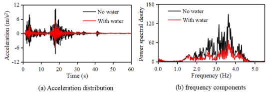
Figure 15. Measurement experiment results (Fukushima earthquake, orifice diameter 30mm).
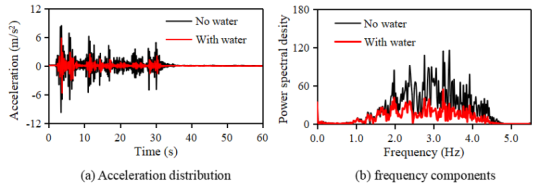
Figure 15 shows the measurement results of the response acceleration obtained from the vibration experiment using a relatively small orifice hole with a diameter of 30mm.
As shown by the comparison of the response accelerations in
Figure 15(a), the response acceleration amplitude of the origami hydraulic damper filled with water was clearly smaller than that of the damper without water. The standard deviation of the response acceleration for the damper without water was 1.46m/s², whereas it was 0.63m/s² for the damper filled with water, confirming a significant reduction of approximately 56.63%.
Furthermore, as shown in the comparison of the frequency components of the response acceleration in
Figure 15(b), across the main frequency range from 1.0 - 5.0 Hz, the frequency response values of the damper filled with water were entirely smaller than those of the damper without water.
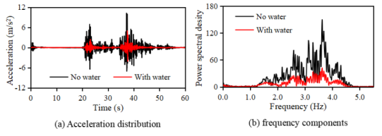
Figure 16. Measurement experiment results (Fukushima earthquake, orifice diameter 50mm).
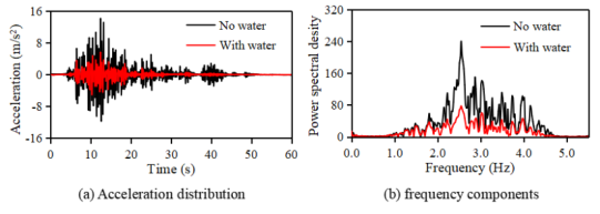
Figure 16 shows the measured response acceleration results obtained from the vibration experiment using a relatively large orifice hole with a diameter of 50mm.
As shown by the comparison of the response accelerations in
Figure 16(a), the response acceleration amplitude of the origami hydraulic damper filled with water was clearly smaller than that of the damper without water. The standard deviation of the response acceleration for the damper without water was 1.44m/s², whereas it was 0.66m/s² for the damper filled with water, confirming a significant reduction of approximately 67.92%.
Furthermore, as shown in the comparison of the frequency components of the response acceleration in
Figure 16(b), across the main frequency range from 1.0 - 5.0 Hz, the frequency response values of the damper filled with water were entirely smaller than those of the damper without water.
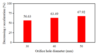
To quantitatively compare the effects of the orifice hole diameter, we compared the reduction rates of the response acceleration values obtained from each experimental case, and the results are summarized in
Figure 17.
The comparison results in
Figure 17 show that when the orifice hole diameters were 30, 40mm, and 50mm, the average reduction rate of the response acceleration for different orifice diameters was 62.68%, indicating a relatively stable and significant vibration control effect.
Figure 17. Results comparing the effect of different orifice hole diameters.
We also confirmed that the damping effect of the origami hydraulic damper increased gradually as the orifice hole diameter increased. In other words, as the orifice hole diameter increased, the fluid on both sides of the mass block flowed more easily, which was considered to be the cause of the increased damping effect of the origami hydraulic damper.
3.3. Influence of Different Earthquake Waves
As described in the previous section, the vibration control effect of the origami hydraulic damper was verified using the Fukushima earthquake waves. However, because earthquake waves are extremely complex, we expect that the vibration control effect may vary significantly depending on different earthquake waves.
Vibration experiments were conducted using different earthquake waves, and the measured response acceleration results were compared with those obtained in the previous sections to investigate the influence of different earthquake waves.
Figure 18. Measurement experiment results (EI Centro NS earthquake, orifice diameter 40mm).
Figure 18 shows the acceleration response results obtained from the vibration experiment using the EI Centro NS earthquake wave.
As shown by the comparison of the response accelerations in
Figure 18(a), the response acceleration amplitude of the origami hydraulic damper filled with water was clearly smaller than that of the damper without water. The standard deviation of the response acceleration for the damper without water was 1.45m/s², whereas that for the damper filled with water was 0.61m/s², indicating a significant reduction of approximately 58.00%.
As shown in the comparison of frequency components of the response acceleration in
Figure 18(b), across the main frequency range of 1.0 - 5.0 Hz, the frequency response values of the damper filled with water were consistently lower than those of the damper without water.
Figure 19. Measurement experiment results (Taft NW earthquake, orifice diameter 40mm).
Figure 19 shows the results of the response acceleration obtained from the vibration test using the Taft NW earthquake wave.
As indicated by the comparison of the response accelerations in
Figure 19(a), the response acceleration amplitude of the origami hydraulic damper filled with water was clearly smaller than that of the damper without water. The standard deviation of the response acceleration for the damper without water was 2.37m/s², whereas that for the damper filled with water was 0.90m/s², demonstrating a significant reduction of approximately 62.16%.
As shown in the comparison of frequency components of the response acceleration in
Figure 19(b), across the main frequency range of 1.0 - 5.0 Hz, the frequency response values of the damper filled with water were consistently lower than those of the damper without water.
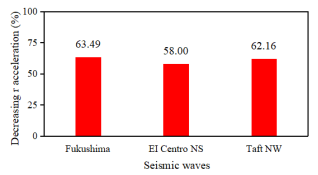
Figure 20. Influence of three types of earthquake waves on the vibration control effect.
Furthermore,
Figure 20 presents a comparison of the vibration control effects of the origami hydraulic damper obtained from the vibration experiments using three different earthquake waves.
As shown in
Figure 20, for the same origami hydraulic damper and experimental setup, the results measured under three different earthquake excitation conditions indicated that even when the external seismic excitation varies, an average reduction rate for different earthquake waves of 61.22% in the response acceleration could be maintained. These experimental measurements confirmed that the damper exhibited a stable vibration control effect.
4. Conclusion
In this study, a novel internal-flow origami hydraulic damper was developed. After the geometric configuration and mechanical characteristics were examined, vibration tests were conducted using the developed experimental setup. The following conclusions were drawn:
1. It was clarified that the damping force generated by the proposed internal flow type origami hydraulic damper is proportional to the square of the motion speed, and a formula for calculating the damping force of the origami hydraulic damper was derived.
2. By sealing liquid in the internal flow type origami hydraulic damper, an effective damping mechanism utilizing internal flow was realized. In addition, it was experimentally confirmed that the damping characteristics can be adjusted by combining ring-shaped parts with different orifice diameters.
3. Vibration experiments were conducted using three types of orifices with diameters of 30mm, 40mm, and 50mm, and the response acceleration was significantly reduced in all cases, with the average reduction rate for the different orifice holes reaching approximately 62.68%.
4. Vibration experiments were conducted using the Fukushima earthquake waves, El Centro NS waves, and Taft NW waves. The results showed that the internal flow-type origami hydraulic damper demonstrated a high vibration control effect in all cases, achieving an average reduction in response acceleration of approximately 61.22%.
Therefore, the internal flow-type origami hydraulic damper proposed in this study has been shown to have a simple structure and good earthquake damping performance, and is expected to be applied to vibration control systems in various industrial fields in the future.