
The frequency response of transistor amplifiers is a key performance characteristic that determines their suitability for broadband and frequency-selective applications. This study comparatively evaluates the performance of a conventional single-stage common-emitter transistor amplifier and a tuned single-stage common-emitter transistor amplifier using NI Multisim 11.0. Both amplifier configurations were designed and simulated under identical operating conditions using a 2N2222A NPN transistor, a 12 V supply, identical biasing networks, and the same passive components. The only design difference was the replacement of the collector resistor in the conventional amplifier with a parallel LC resonant circuit in the tuned amplifier. The frequency response of both amplifiers was evaluated over the frequency range of 10 Hz to 100 MHz, and the voltage gains were calculated from the simulated output waveforms and expressed in decibels (dB). The results showed that the conventional amplifier maintained a nearly constant mid-band gain of approximately 54 dB over a wide frequency range, demonstrating excellent broadband performance. In contrast, the tuned amplifier produced a maximum gain of approximately 72.04 dB at its designed resonant frequency of 1 kHz, but exhibited a much narrower bandwidth due to its frequency-selective characteristics. The comparative analysis confirms that the conventional amplifier is better suited for broadband signal amplification, whereas the tuned amplifier is more appropriate for narrow-band and radio-frequency applications requiring high gain at a specific frequency. These findings provide useful guidance for selecting suitable transistor amplifier configurations for broadband and frequency-selective electronic and communication applications.
| Published in | Journal of Electrical and Electronic Engineering (Volume 14, Issue 5) |
| DOI | 10.11648/j.jeee.20261405.11 |
| Page(s) | 211-222 |
| Creative Commons |
This is an Open Access article, distributed under the terms of the Creative Commons Attribution 4.0 International License (http://creativecommons.org/licenses/by/4.0/), which permits unrestricted use, distribution and reproduction in any medium or format, provided the original work is properly cited. |
| Copyright |
Copyright © The Author(s), 2026. Published by Science Publishing Group |
Common-emitter Transistor Amplifier, Tuned Amplifier, Frequency Response, Bandwidth, Resonant Frequency, Voltage Gain, Bode Magnitude Plot, Small-signal Amplifier
Frequency | Input Voltage (mVp) | Conventional Amplifier Output | Voltage Gain (V/V) | Gain (dB) | Tuned Amplifier Output | Voltage Gain (V/V) | Gain (dB) |
|---|---|---|---|---|---|---|---|
10Hz | 10 | 24 | 2.40 | 7.60 | 0.25 | 0.025 | -32.04 |
15Hz | 10 | 44 | 4.40 | 12.87 | 1.45 | 0.145 | -16.77 |
100Hz | 10 | 800 | 80.00 | 38.06 | 170 | 17.00 | 24.61 |
200Hz | 10 | 1600 | 160.00 | 44.08 | 690 | 69.00 | 36.78 |
500Hz | 10 | 3250 | 325.00 | 50.24 | 4000 | 400.00 | 52.04 |
1KHz | 10 | 4000 | 400.00 | 52.04 | 40000 | 4000.00 | 72.04 |
10KHz | 10 | 4700 | 470.00 | 53.44 | 2500 | 250.00 | 47.96 |
100KHz | 10 | 5000 | 500.00 | 53.98 | 124 | 12.40 | 21.87 |
1MHz | 10 | 5000 | 500.00 | 53.98 | 12.5 | 1.25 | 1.94 |
10MHz | 10 | 4500 | 450.00 | 53.06 | 1.25 | 0.125 | -18.06 |
20MHz | 10 | 3750 | 375.00 | 51.48 | 0.95 | 0.095 | -20.45 |
50MHz | 10 | 2750 | 275.00 | 48.79 | 0.25 | 0.025 | -32.04 |
100MHz | 10 | 1500 | 150.00 | 43.52 | 0.1 | 0.010 | -40.00 |
AC | Alternating Current |
BJT | Bipolar Junction Transistor |
CE | Common-Emitter |
DC | Direct Current |
IF | Intermediate Frequency |
LC | Inductor–Capacitor |
NI | National Instruments |
RF | Radio Frequency |
| Voltage Gain |
| Emitter Bypass Capacitor |
| Input Coupling Capacitor |
| Output Coupling Capacitor |
| Base Current |
| Collector Current |
| Emitter Current |
| Voltage-Divider Bias Resistors |
| Collector Resistor |
| Emitter Resistor |
| Source Resistance |
| Base Voltage |
| Base–Emitter Voltage |
| Supply Voltage |
| Collector–Emitter Voltage |
| Emitter Voltage |
| Capacitive Reactance |
| Inductive Reactance |
| Resonant Frequency |
| [1] | Boylestad, R. L., & Nashelsky, L. (2019). Electronic Devices and Circuit Theory (12th ed.). Pearson. |
| [2] | Cadiz, F., & Couairon, A. (2025). Electric Currents, Ohm’s Law and Electrical Networks. In Classical Electrodynamics: Fundamentals and Applications (pp. 215-266): Springer. |
| [3] | Campos-Salazar, J. M., Aguayo-Lazcano, J. L., Rafiezadeh, R., & García-Rojas, G. (2025). Bipolar Junction Transistor Amplifiers—State-Space Modeling Across Frequencies. Journal of Electronics and Electrical Engineering. |
| [4] | Casali, N., Cardani, L., Colantoni, I., Cruciani, A., Di Domizio, S., Martinez, M, Vignati, M. (2019). Phonon and light read out of a Li 2 MoO 4 crystal with multiplexed kinetic inductance detectors. The European Physical Journal C, 79(8), 724. |
| [5] | Chen, C.-C. (2020). New method of finding exact frequency response for feedback amplifiers. IET Circuits, Devices & Systems, 14(7), 1048–1061. |
| [6] | Christensen, D. A. (2022). Kirchhoff’s Voltage and Current Laws: Circuit Analysis. In Introduction to Biomedical Engineering: Biomechanics and Bioelectricity Part II (pp. 13-23): Springer. |
| [7] | Clark, J. (2012). AC power conditioners: Design and application: Academic Press. |
| [8] | Costa, L. d. F. (2018). Linearity Analysis of the Common Collector Amplifier, or Emitter Follower. arXiv preprint arXiv: 1805.02705. |
| [9] | Floyd, T. L. (2021). Electronic Devices (11th ed.). Pearson. |
| [10] | Gift, S. J., & Maundy, B. (2020). Bipolar Junction Transistor. In Electronic Circuit Design and Application (pp. 41-87): Springer. |
| [11] | Horowitz, P., & Hill, W. (2015). The Art of Electronics (3rd ed.). Cambridge University Press. |
| [12] | Leblebici, D., & Leblebici, Y. (2021). Frequency-Selective RF Circuits. In Fundamentals of High Frequency CMOS Analog Integrated Circuits (pp. 165-216): Springer. |
| [13] | Litovski, V. (2023). 2 Biasing the Basic Electronic Amplifier Configurations. In Lecture Notes in Analogue Electronics: Electronic Signal Amplification and Linear Oscillators (pp. 5-39): Springer. |
| [14] | Manocha, P., & Rincón-Mora, G. A. (2025). Transistor Frequency-Response Analysis: Recursive Shunt-Circuit Transformations. Electronics, 14(2), 296. |
| [15] | Mercer, D., & Miclaus, A. (2020). ADALM2000 Activity: Frequency Response of a Common-Emitter BJT Amplifier. Analog Dialogue, 54(2). |
| [16] | Moses, G. E., & Ebregbe, D. (2025). Design, Simulation and Performance Comparison of Four Single-Stage Amplifier Configurations. International Journal of Academic Engineering Research, 9(8), 166–179. |
| [17] | National Instruments. (2010). NI Multisim User Guide. National Instruments. |
| [18] | Noor, K. T., Islam, M. S., & Fuad, F. (2016). Analysis of power converters and smart power factor correction. BRAC University, |
| [19] | Ruiz, D. (2010). Discrete time disturbance accommodation control of a buck-boost switching converter: University of Arkansas. |
| [20] | Ryan, B. (2013). High Impedance Amplifiers for Non-Contact Bio-Potential Sensing. Open Access Te Herenga Waka-Victoria University of Wellington. |
| [21] | Sapkota, M. (2026). Verification of Bias Circuit Design of Different Bipolar RF Transistors. |
| [22] | Sedra, A. S., & Smith, K. C. (2021). Microelectronic Circuits (8th ed.). Oxford University Press. |
| [23] | Self, D. (2013). Audio power amplifier design: Routledge. |
| [24] | Sobot, R. (2013). RF and IF Amplifiers: Solutions. In Wireless Communication Electronics by Example (pp. 201-213): Springer. |
| [25] | Strickland, J. R. (2016). Collector, Base, and Emitter. In Junk Box Arduino: Ten Projects in Upcycled Electronics (pp. 103-124): Springer. |
| [26] | Van Rensburg, P. J., & Ferreira, H. C. (2003). Coupling circuitry: Understanding the functions of different components. Paper presented at the Proc. 7th Int. Symp. Power-Line Comm. |
| [27] | Wang, R. (2025). Research on Performance Improvement of Common-Emitter Amplifiers Based on Bias Design Optimization. Paper presented at the 2025 7th International Conference on Electronic Engineering and Informatics (EEI). |
| [28] | Wardhana, A. W., Ramadhani, Y., & Priswanto, P. (2022). Design and Simulation of a Multistages Common-Emitter, Common-Collector, AC Voltage Amplifier. Jurnal Nasional Teknik Elektro. |
| [29] | Yusuf, A. i., Widada, W., & Taruno, W. P. (2022). Determine of the time constant of capacitance applied to electrical capacitance tomography. Paper presented at the 2022 International Conference on Informatics Electrical and Electronics (ICIEE). |
APA Style
Abdullahi, Y., Saidu, I. G., Abdullahi, M. B., Dabai, K. A., Sahabi, B. B., et al. (2026). Comparative Performance Evaluation of Conventional and Tuned Single-Stage Common-Emitter Transistor Amplifiers Using Multisim 11.0. Journal of Electrical and Electronic Engineering, 14(5), 211-222. https://doi.org/10.11648/j.jeee.20261405.11
ACS Style
Abdullahi, Y.; Saidu, I. G.; Abdullahi, M. B.; Dabai, K. A.; Sahabi, B. B., et al. Comparative Performance Evaluation of Conventional and Tuned Single-Stage Common-Emitter Transistor Amplifiers Using Multisim 11.0. J. Electr. Electron. Eng. 2026, 14(5), 211-222. doi: 10.11648/j.jeee.20261405.11
@article{10.11648/j.jeee.20261405.11,
  author = {Yusuf Abdullahi and Ismail Garba Saidu and Muhammad Bello Abdullahi and Kabir Ahmed Dabai and Buhari Bello Sahabi and Aisha Aminu Mode},
  title = {Comparative Performance Evaluation of Conventional and Tuned Single-Stage Common-Emitter Transistor Amplifiers Using Multisim 11.0},
  journal = {Journal of Electrical and Electronic Engineering},
  volume = {14},
  number = {5},
  pages = {211-222},
  doi = {10.11648/j.jeee.20261405.11},
  url = {https://doi.org/10.11648/j.jeee.20261405.11},
  eprint = {https://article.sciencepublishinggroup.com/pdf/10.11648.j.jeee.20261405.11},
  abstract = {The frequency response of transistor amplifiers is a key performance characteristic that determines their suitability for broadband and frequency-selective applications. This study comparatively evaluates the performance of a conventional single-stage common-emitter transistor amplifier and a tuned single-stage common-emitter transistor amplifier using NI Multisim 11.0. Both amplifier configurations were designed and simulated under identical operating conditions using a 2N2222A NPN transistor, a 12 V supply, identical biasing networks, and the same passive components. The only design difference was the replacement of the collector resistor in the conventional amplifier with a parallel LC resonant circuit in the tuned amplifier. The frequency response of both amplifiers was evaluated over the frequency range of 10 Hz to 100 MHz, and the voltage gains were calculated from the simulated output waveforms and expressed in decibels (dB). The results showed that the conventional amplifier maintained a nearly constant mid-band gain of approximately 54 dB over a wide frequency range, demonstrating excellent broadband performance. In contrast, the tuned amplifier produced a maximum gain of approximately 72.04 dB at its designed resonant frequency of 1 kHz, but exhibited a much narrower bandwidth due to its frequency-selective characteristics. The comparative analysis confirms that the conventional amplifier is better suited for broadband signal amplification, whereas the tuned amplifier is more appropriate for narrow-band and radio-frequency applications requiring high gain at a specific frequency. These findings provide useful guidance for selecting suitable transistor amplifier configurations for broadband and frequency-selective electronic and communication applications.},
 year = {2026}
}
TY  - JOUR
T1  - Comparative Performance Evaluation of Conventional and Tuned Single-Stage Common-Emitter Transistor Amplifiers Using Multisim 11.0
AU  - Yusuf Abdullahi
AU  - Ismail Garba Saidu
AU  - Muhammad Bello Abdullahi
AU  - Kabir Ahmed Dabai
AU  - Buhari Bello Sahabi
AU  - Aisha Aminu Mode
Y1  - 2026/09/09
PY  - 2026
N1  - https://doi.org/10.11648/j.jeee.20261405.11
DO  - 10.11648/j.jeee.20261405.11
T2  - Journal of Electrical and Electronic Engineering
JF  - Journal of Electrical and Electronic Engineering
JO  - Journal of Electrical and Electronic Engineering
SP  - 211
EP  - 222
PB  - Science Publishing Group
SN  - 2329-1605
UR  - https://doi.org/10.11648/j.jeee.20261405.11
AB  - The frequency response of transistor amplifiers is a key performance characteristic that determines their suitability for broadband and frequency-selective applications. This study comparatively evaluates the performance of a conventional single-stage common-emitter transistor amplifier and a tuned single-stage common-emitter transistor amplifier using NI Multisim 11.0. Both amplifier configurations were designed and simulated under identical operating conditions using a 2N2222A NPN transistor, a 12 V supply, identical biasing networks, and the same passive components. The only design difference was the replacement of the collector resistor in the conventional amplifier with a parallel LC resonant circuit in the tuned amplifier. The frequency response of both amplifiers was evaluated over the frequency range of 10 Hz to 100 MHz, and the voltage gains were calculated from the simulated output waveforms and expressed in decibels (dB). The results showed that the conventional amplifier maintained a nearly constant mid-band gain of approximately 54 dB over a wide frequency range, demonstrating excellent broadband performance. In contrast, the tuned amplifier produced a maximum gain of approximately 72.04 dB at its designed resonant frequency of 1 kHz, but exhibited a much narrower bandwidth due to its frequency-selective characteristics. The comparative analysis confirms that the conventional amplifier is better suited for broadband signal amplification, whereas the tuned amplifier is more appropriate for narrow-band and radio-frequency applications requiring high gain at a specific frequency. These findings provide useful guidance for selecting suitable transistor amplifier configurations for broadband and frequency-selective electronic and communication applications.
VL  - 14
IS  - 5
ER  -
Department of Applied Physics, Umaru Ali Shinkafi Polytechnic, Sokoto, Nigeria
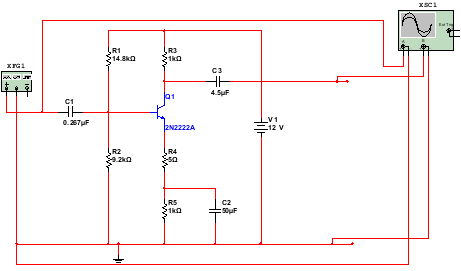
Figure 1. Conventional single-stage common-emitter transistor amplifier.
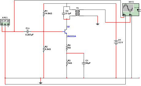
Figure 2. Single-stage tuned common-emitter transistor amplifier.
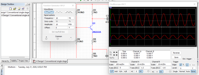
Figure 3. Conventional Single-Stage Common Emitter Transistor Amplifier Waveform.
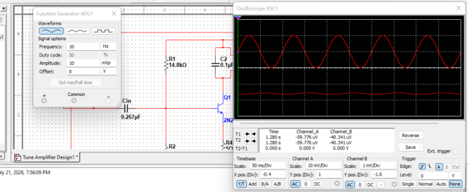
Figure 4. Single-Stage Tuned Common-Emitter Transistor Amplifier Waveform.
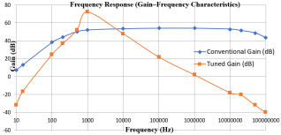
Figure 5. Bode magnitude plot comparing the frequency response of the conventional single-stage common-emitter transistor amplifier and the single-stage tuned common-emitter transistor amplifier.

Information



 Share This Article
 Twitter
 Linked In
 Facebook
 Copy
Copy Download