This article presents the mathematical modelling of the national power grid of the Republic of Congo-Brazzaville and its future behaviour following the integration of the Sounda Gorges hydroelectric power plant. The network is simulated using the PSAT 2.1.11 software on a model comprising 45 buses, 27 lines, 19 transformers and 5 generators. The nodal admittance matrix [Ybus] equations and the active power transit equations Pik and reactive power transit equations Qik are developed. Three scenarios are simulated: a full network configuration with the C.E.C and AKSA thermal power plants, a full network configuration with the Congo Electric Power Plant (C.E.C) operating at one-third of its rated capacity, and an all-hydro network configuration without the thermal power plants. The PSAT simulations reveal critical results for network planning, notably the presence of at least 11 out of 45 buses exhibiting voltages below the regulatory threshold of 0.95 p.u. across all three scenarios, regardless of the presence or absence of the C.E.C and AKSA thermal power plants. Sounda will only be able to operate at its full rated capacity of 800 MW with an interconnection to the Central African Power Pool (CAPP), given that the current national demand, including losses (545.6 MW), is lower than the total available generating capacity.
| Published in | Science Journal of Energy Engineering (Volume 14, Issue 2) |
| DOI | 10.11648/j.sjee.20261402.13 |
| Page(s) | 47-64 |
| Creative Commons |
This is an Open Access article, distributed under the terms of the Creative Commons Attribution 4.0 International License (http://creativecommons.org/licenses/by/4.0/), which permits unrestricted use, distribution and reproduction in any medium or format, provided the original work is properly cited. |
| Copyright |
Copyright © The Author(s), 2026. Published by Science Publishing Group |
Sounda Gorges Hydroelectric Power Plant, CEC 470 MW, AKSA 50 MW, Newton-Raphson, Voltage Stability, Power Flow
Characteristic | Value |
|---|---|
Configuration | 4 Francis turbines |
Rated flow per turbine | 322.71 m³/s |
Turbine efficiency | 92.0% |
Unit turbine power | 194.52 MW |
Total installed capacity | 778.08 MW |
Overall efficiency | 89.7% |
Flood / low-water power | 624.89 MW / 261.48 MW |
Annual energy production | 4352.45 GWh |
Capacity factor | 64.7% |
Parameter | Symbol | Value | Unit |
|---|---|---|---|
Total installed power | P | 800 | MW |
Number of Francis units | N | 4 | - |
Power per unit | Punit | 200 | MW |
Apparent power per unit | Sunit | 222 | MVA |
Gross head | Hb | 75.0 | m |
Net head | Hn | 68.5 | m |
Head losses | Δh = Hb − Hn | 6.5 | m |
Maximum gross flow (flood) | Qbmax | 1129.5 | m³/s |
Maximum turbined flow (flood) | Qtmax | 1 036 | m³/s |
Annual average turbined flow | Qtann | 835.7 | m³/s |
Reserved (ecological) flow | Qres | 92.8 | m³/s |
Flow per unit (nominal) | Qunit = Qann/4 | 208.9 | m³/s |
Overall efficiency | η | 91.4 | % |
Rotation speed (Francis) | n | 150 | tr/min |
Specific speed (IEC 60193) | Ns | 272 | - |
Alternator output voltage | Ustator | 13.8 | kV |
Grid connection voltage | Unetwork | 400 | kV |
Transformation ratio | m | 13.8 / 400 | kV/kV |
Nominal power factor | cos φ | 0.90 | - |
Nominal reactive power | Qr | 387 | MVAR |
Grid frequency | f | 50 | Hz |
400 kV lines (ACSR 455 mm²) | 220 kV lines (ACSR 500 mm²) | 110 kV lines (ACSR 500 mm²) | |
|---|---|---|---|
|
|
|
|
|
|
| 0.1133 mH/km |
|
|
|
|
|
|
|
|
|
|
|
|
Branch | Voltage (kV) | Length (km) | R (p.u) | X (p.u) | B (p.u) |
|---|---|---|---|---|---|
SOUNDA–POSTE-IN | 400 | 71.7 | 0.00134 | 0.01267 | 0.4325 |
POSTE-IN-MGK2 | 220 | 14.0 | 0.00145 | 0.00909 | 0.0234 |
AKSA-NGOYO | 220 | 9.36 | 0.00097 | 0.00608 | 0.0157 |
NGOYO-MGK1 | 220 | 12.0 | 0.00124 | 0.00779 | 0.0201 |
MGK1-MGK2 | 220 | 4.0 | 0.00041 | 0.00260 | 0.0067 |
C.E.C-MGK2 (×2) | 220 | 19.2 | 0.00198 | 0.01246 | 0.0321 |
MGK2-MBOUNDI | 220 | 37.5 | 0.00387 | 0.02434 | 0.0627 |
MBOUNDI-LOUDIMA | 220 | 133.0 | 0.01374 | 0.08633 | 0.2225 |
LOUDIMA-MINDOULI | 220 | 150.0 | 0.01550 | 0.09736 | 0.2509 |
MINDOULI-TSIELAMPO | 220 | 105.0 | 0.01085 | 0.06815 | 0.1756 |
TSIELAMPO-DJIRI | 220 | 22.0 | 0.00227 | 0.01428 | 0.0368 |
DJIRI-MALOUKOU | 220 | 13.0 | 0.00134 | 0.00844 | 0.0217 |
MALOUKOU-NGO | 220 | 194.0 | 0.02004 | 0.12592 | 0.3245 |
NGO-GAMBOMA | 220 | 75.2 | 0.00777 | 0.04881 | 0.1258 |
GAMBOMA-OYO | 220 | 87.6 | 0.00905 | 0.05686 | 0.1465 |
IMBOULOU-NGO (×2) | 220 | 77.5 | 0.00801 | 0.05030 | 0.1296 |
MBOUONO-TSIELAMPO | 220 | 13.2 | 0.00136 | 0.00857 | 0.0221 |
OYO-OWANDO | 110 | 97.0 | 0.04650 | 0.28539 | 0.0352 |
OYO-BOUNDJI | 110 | 91.0 | 0.04362 | 0.26774 | 0.0330 |
BOUNDJI-EWO | 110 | 75.0 | 0.03595 | 0.22066 | 0.0272 |
LOUDIMA-NKAYI | 110 | 24.59 | 0.01179 | 0.07235 | 0.0089 |
NKAYI-BOUENZA II | 110 | 56.2 | 0.02694 | 0.16535 | 0.0204 |
BOUENZA II-DANGOTE | 110 | 11.0 | 0.00527 | 0.03236 | 0.0040 |
DANGOTE-MOUKOUKOULOU | 110 | 30.0 | 0.01438 | 0.08826 | 0.0109 |
NGO-DJAMBALA | 110 | 109.0 | 0.05225 | 0.32069 | 0.0396 |
Busbar Type | Known Variables | Unknown Variables | Nodes |
|---|---|---|---|
Load (P, Q) | P, Q | , | 20 HTB substations (Ngoyo, MGK1/2, Mboundi.) |
Control (P, V) | P, | Q, | C.E.C, AKSA, Imboulou, Moukoukoulou |
Reference (slack) | , | P, Q | Sounda 400 kV Bus |
PSAT | Power Systems Analysis Toolbox |
EEC | Congolese Electric Energy |
SNE | National Electricity Company |
C.E.C | Congo Electric Plant |
GT | Gas Turbine |
CCGT | Combined-cycle Gas Turbine |
HV | High Voltage |
EHV | Extra High Voltage (Very High Voltage) |
PEAC | Central Africa Energy Pool (CAPP) |
PQ | Load Bus -active Power P and Reactive Power Q Specified |
PV | Generator Bus-active Power P and Voltage Magnitude V Specified |
p.u | Per-unit (Normalised Value, Base 100 MVA / Rated Voltage) |
MVA | Megavolt-Ampere (Apparent Power) |
MW | Megawatt (Active Power) |
MVAR | Megavar (Reactive Power) |
Busbars | Scenario 1 (V) | Scenario 2 (V) | Scenario 3 (V) | Threshold | Type |
|---|---|---|---|---|---|
SOUNDA 400 kV (slack) | 1.000 | 1.000 | 1.000 | ≥0.95 | Slack |
CEC 220 kV | 1.000 | 1.000 | 1.000 | PV | PV |
AKSA 220 kV (TAG Djeno) | 1.000 | 1.000 | 1.000 | PV | PV |
IMBOULOU 220 kV | 1.000 | 1.000 | 1.000 | PV | PV |
MOUKOUKOULOU 110 kV | 1.000 | 1.000 | 1.000 | PV | PV |
POSTE-IN 220 kV | 1.001 | 0.949 | 1.000 | 0.95 | PQ |
NGOYO 220 kV | 0.995 | 0.989 | 1.000 | 0.95 | PQ |
MGK2 220 kV | 0.991 | 0.974 | 0.990 | 0.95 | PQ |
MGK1 220 kV | 0.990 | 0.976 | 0.976 | 0.95 | PQ |
MBOUNDI 220 kV | 0.970 | 0.951 | 0.911 | 0.95 | PQ |
BOUENZA II 110 kV | 0.979 | 0.976 | 0.976 | 0.95 | PQ |
DANGOTE 110 kV | 0.992 | 0.991 | 0.991 | 0.95 | PQ |
NKAYI 110 kV | 0.940 | 0.925 | 0.911 | 0.95 | PQ |
LOUDIMA 220 kV | 0.922 | 0.897 | 0.753 | 0.95 | PQ |
MINDOULI 220 kV | 0.869 | 0.838 | 0.629 | 0.95 | PQ |
TSIELAMPO 220 kV | 0.849 | 0.821 | 0.647 | 0.95 | PQ |
MALOUKOU 220 kV (Braz.) | 0.869 | 0.843 | 0.688 | 0.95 | PQ |
MBOUONO 220 kV | 0.848 | 0.820 | 0.646 | 0.95 | PQ |
DJIRI 220 kV | 0.859 | 0.833 | 0.670 | 0.95 | PQ |
DJAMBALA 110 kV | 0.989 | 0.984 | 0.984 | 0.95 | PQ |
GAMBOMA 220 kV | 0.971 | 0.965 | 0.936 | 0.95 | PQ |
NGO TR2 (load) | 0.981 | 0.976 | 0.976 | 0.95 | PQ |
OYO TR2 (load) | 0.940 | 0.933 | 0.920 | 0.95 | PQ |
OWANDO 110 kV | 0.909 | 0.901 | 0.868 | 0.95 | PQ |
BOUNDJI 110 kV | 0.942 | 0.934 | 0.902 | 0.95 | PQ |
EWO 110 kV | 0.945 | 0.937 | 0.905 | 0.95 | PQ |
| [1] | P. Kundur, Power System Stability and Control. New York: McGraw-Hill (EPRI), 1994. |
| [2] | Bowassa-Bob, Y. P., Lidinga Mobonda, F., Ngoma Mvoundou, C., Pasi Bengi Masata, A. and Nsongo, T. (2026) Modeling of Hydrodynamic Parameters of the Kouilou-Niari River for Energy Efficiency of the Sounda Gorges Hydroelectric Power Plant in Republic of Congo. Journal of Power and Energy Engineering, 14, 59-81. |
| [3] | E²C (Congolese Electric Energy), Annual Report on Electricity Production and Distribution. Brazzaville: E2C, 2021. |
| [4] | W. F. Tinney and C. E. Hart, “Power Flow Solution by Newton’s Method,” IEEE Transactions on Power Apparatus and Systems, vol. PAS-86, no. 11, pp. 1449–1460, Nov. 1967. |
| [5] | V. Ajjarapu and C. Christy, The continuation power flow: a tool for steady state voltage stability analysis, in IEEE Transactions on Power Systems, vol. 7, no. 1, pp. 416-423, Feb. 1992. |
| [6] | F. Milano, “An Open Source Power System Analysis Toolbox,” IEEE Transactions on Power Systems, vol. 20, no. 3, pp. 1199–1206, Aug. 2005. |
| [7] | IEC 60193: 2019, Hydraulic Turbines, Storage Pumps and Pump-Turbines-Model Acceptance Tests, 3rd ed. International Electrotechnical Commission, Geneva, 2019. |
| [8] | C. C. Warnick, Hydropower Engineering. Prentice-Hall, Englewood Cliffs NJ, 1984. |
| [9] | B. M. Weedy, B. J. Cory, N. Jenkins, J. Ekanayake and G. Strbac, Electric Power Systems. Wiley, 5th ed., 2012. |
| [10] | J. D. Glover, M. S. Sarma and T. J. Overbye, Power Systems Analysis and Design, 6th ed. Cengage Learning, 2017. |
| [11] | N. G. Hingorani and L. Gyugyi, Understanding FACTS: Concepts and Technology of Flexible AC Transmission Systems. IEEE Press, New York, 2000. |
| [12] | W. D. Stevenson, Elements of Power System Analysis, 4th ed. McGraw-Hill, 1982. |
| [13] | H. Saadat, Power System Analysis. McGraw-Hill, 3rd ed., 2010. |
| [14] | T. Van Cutsem and C. Vournas, Voltage Stability of Electric Power Systems. Kluwer Academic Publishers (Springer), Boston, 1998. |
| [15] | EN 50160: 2010+A3: 2019, Voltage Characteristics of Electricity Supplied by Public Electricity Networks. CENELEC, Brussels, 2019. |
| [16] | A. J. Wood, B. F. Wollenberg and G. B. Sheblié, Power Generation, Operation, and Control. Wiley, 3rd ed., 2014. |
| [17] |
Central Africa Power Pool, Project situation in the portfolio of the Central Africa Power Pool (CAPP) Luanda, 2024.
https://peac-ac.org/wp-content/uploads/2024/03/Situation_projet_2024.pdf |
APA Style
Bowassa-Bob, Y. P., Gomba, R., Mobonda, F. L., Ngulumingi, C. V., Nsongo, T., et al. (2026). Impact of the Sounda Gorge Hydropower Plant on Power Flow and Voltage Stability of the Congo-Brazzaville Electrical Network Under PSAT. Science Journal of Energy Engineering, 14(2), 47-64. https://doi.org/10.11648/j.sjee.20261402.13
ACS Style
Bowassa-Bob, Y. P.; Gomba, R.; Mobonda, F. L.; Ngulumingi, C. V.; Nsongo, T., et al. Impact of the Sounda Gorge Hydropower Plant on Power Flow and Voltage Stability of the Congo-Brazzaville Electrical Network Under PSAT. Sci. J. Energy Eng. 2026, 14(2), 47-64. doi: 10.11648/j.sjee.20261402.13
@article{10.11648/j.sjee.20261402.13,
  author = {Yves Pancrace Bowassa-Bob and Rodolphe Gomba and Flory Lidinga Mobonda and Christian Vunda Ngulumingi and Timothee Nsongo and Andre Pasi Bengi Masata and Verlan Chrice Ikama},
  title = {Impact of the Sounda Gorge Hydropower Plant on Power Flow and Voltage Stability of the Congo-Brazzaville Electrical Network Under PSAT},
  journal = {Science Journal of Energy Engineering},
  volume = {14},
  number = {2},
  pages = {47-64},
  doi = {10.11648/j.sjee.20261402.13},
  url = {https://doi.org/10.11648/j.sjee.20261402.13},
  eprint = {https://article.sciencepublishinggroup.com/pdf/10.11648.j.sjee.20261402.13},
  abstract = {This article presents the mathematical modelling of the national power grid of the Republic of Congo-Brazzaville and its future behaviour following the integration of the Sounda Gorges hydroelectric power plant. The network is simulated using the PSAT 2.1.11 software on a model comprising 45 buses, 27 lines, 19 transformers and 5 generators. The nodal admittance matrix [Ybus] equations and the active power transit equations Pik and reactive power transit equations Qik are developed. Three scenarios are simulated: a full network configuration with the C.E.C and AKSA thermal power plants, a full network configuration with the Congo Electric Power Plant (C.E.C) operating at one-third of its rated capacity, and an all-hydro network configuration without the thermal power plants. The PSAT simulations reveal critical results for network planning, notably the presence of at least 11 out of 45 buses exhibiting voltages below the regulatory threshold of 0.95 p.u. across all three scenarios, regardless of the presence or absence of the C.E.C and AKSA thermal power plants. Sounda will only be able to operate at its full rated capacity of 800 MW with an interconnection to the Central African Power Pool (CAPP), given that the current national demand, including losses (545.6 MW), is lower than the total available generating capacity.},
 year = {2026}
}
TY  - JOUR
T1  - Impact of the Sounda Gorge Hydropower Plant on Power Flow and Voltage Stability of the Congo-Brazzaville Electrical Network Under PSAT
AU  - Yves Pancrace Bowassa-Bob
AU  - Rodolphe Gomba
AU  - Flory Lidinga Mobonda
AU  - Christian Vunda Ngulumingi
AU  - Timothee Nsongo
AU  - Andre Pasi Bengi Masata
AU  - Verlan Chrice Ikama
Y1  - 2026/06/18
PY  - 2026
N1  - https://doi.org/10.11648/j.sjee.20261402.13
DO  - 10.11648/j.sjee.20261402.13
T2  - Science Journal of Energy Engineering
JF  - Science Journal of Energy Engineering
JO  - Science Journal of Energy Engineering
SP  - 47
EP  - 64
PB  - Science Publishing Group
SN  - 2376-8126
UR  - https://doi.org/10.11648/j.sjee.20261402.13
AB  - This article presents the mathematical modelling of the national power grid of the Republic of Congo-Brazzaville and its future behaviour following the integration of the Sounda Gorges hydroelectric power plant. The network is simulated using the PSAT 2.1.11 software on a model comprising 45 buses, 27 lines, 19 transformers and 5 generators. The nodal admittance matrix [Ybus] equations and the active power transit equations Pik and reactive power transit equations Qik are developed. Three scenarios are simulated: a full network configuration with the C.E.C and AKSA thermal power plants, a full network configuration with the Congo Electric Power Plant (C.E.C) operating at one-third of its rated capacity, and an all-hydro network configuration without the thermal power plants. The PSAT simulations reveal critical results for network planning, notably the presence of at least 11 out of 45 buses exhibiting voltages below the regulatory threshold of 0.95 p.u. across all three scenarios, regardless of the presence or absence of the C.E.C and AKSA thermal power plants. Sounda will only be able to operate at its full rated capacity of 800 MW with an interconnection to the Central African Power Pool (CAPP), given that the current national demand, including losses (545.6 MW), is lower than the total available generating capacity.
VL  - 14
IS  - 2
ER  -
Polytechnic Superior National School (ENSP), Marien Ngouabi University, Brazzaville, Congo
Polytechnic Superior National School (ENSP), Marien Ngouabi University, Brazzaville, Congo
Laboratory of Electrical Engineering Department, Higher Institute of Applied Techniques-Kinshasa (ISTA-Kinshasa), Kinshasa, Democratic Republic of the Congo (DRC)
Laboratory of Electrical Engineering Department, Higher Institute of Applied Techniques-Kinshasa (ISTA-Kinshasa), Kinshasa, Democratic Republic of the Congo (DRC)
Faculty of Sciences and Techniques, Marien Ngouabi University, Brazzaville, Congo
Laboratory of Electrical Engineering Department, Higher Institute of Applied Techniques-Kinshasa (ISTA-Kinshasa), Kinshasa, Democratic Republic of the Congo (DRC)
Polytechnic Superior National School (ENSP), Marien Ngouabi University, Brazzaville, Congo
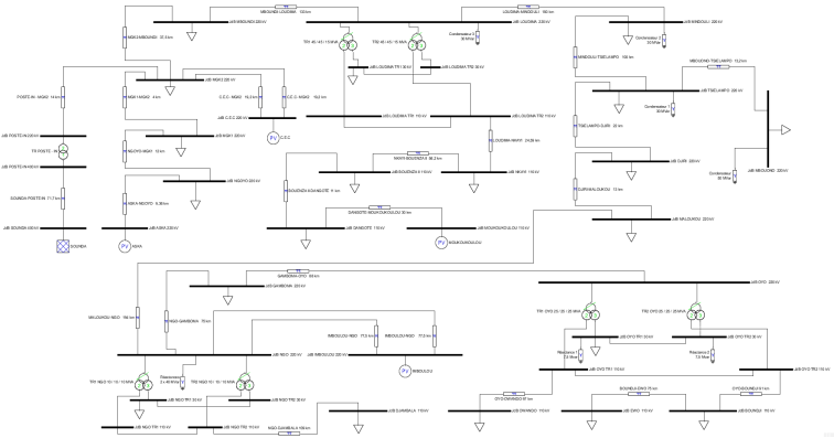
Figure 1. Sounda Model Connected to the National Electricity Grid of Congo.
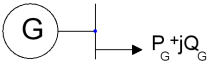
Figure 2. Generator model.
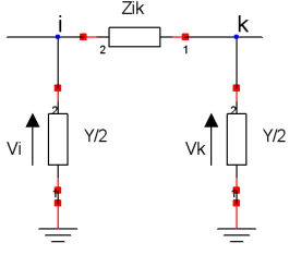
Figure 3. Transmission Line Model (π-equivalent circuit).
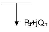
Figure 4. Electrical Load Model.
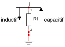
Figure 5. Shunt Element Model.
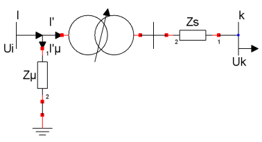
Figure 6. Two-Winding Transformer Model.
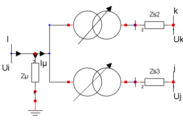
Figure 7. Three-Winding Transformer Model.
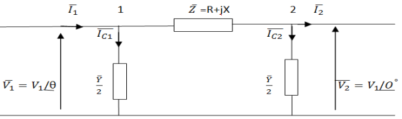
Figure 8. Equivalent Model of an EHV Line with Distributed Parameters.
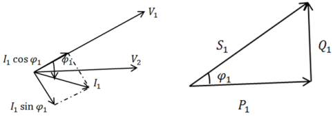
Figure 9. Voltage diagram and power triangle.
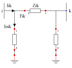
Figure 10. Line model.
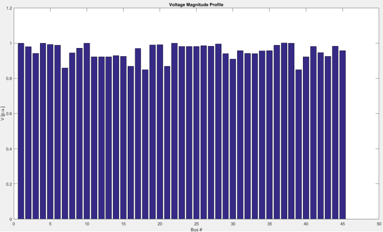
Figure 11. Network voltage profile curve (Scenario 1: full grid with C.E.C and AKSA).
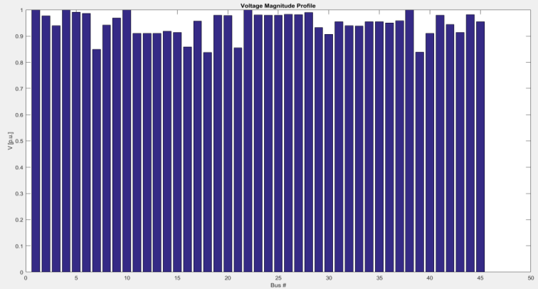
Figure 12. Voltage Profile Curve without Thermal Plants (Scénario 2).
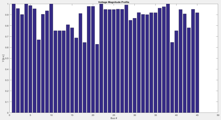
Figure 13. Voltage Profile Curve (Scenario 3: C.E.C at one-third power).
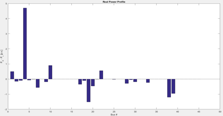
Figure 14. Active Power Flow Curve (Scenario 1).
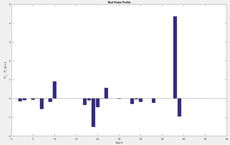
Figure 15. Active Power Flow Curve (Scenario 2).
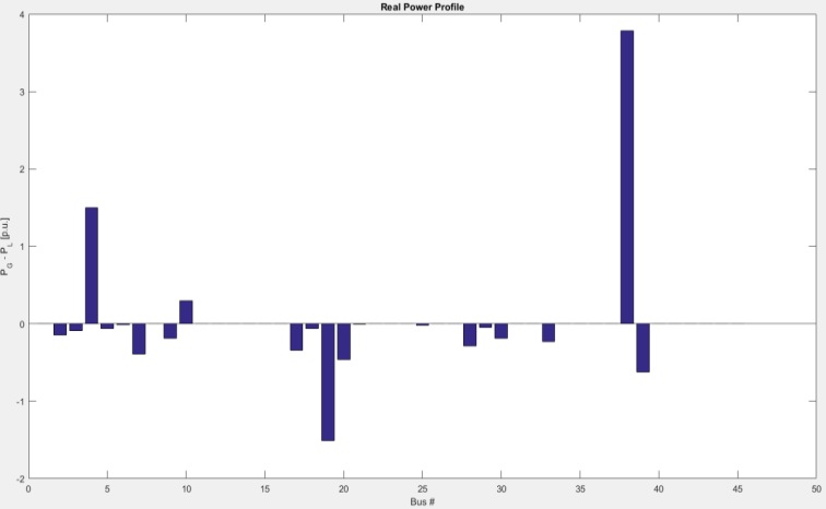
Figure 16. Active Power Flow Curve (Scenario 1).
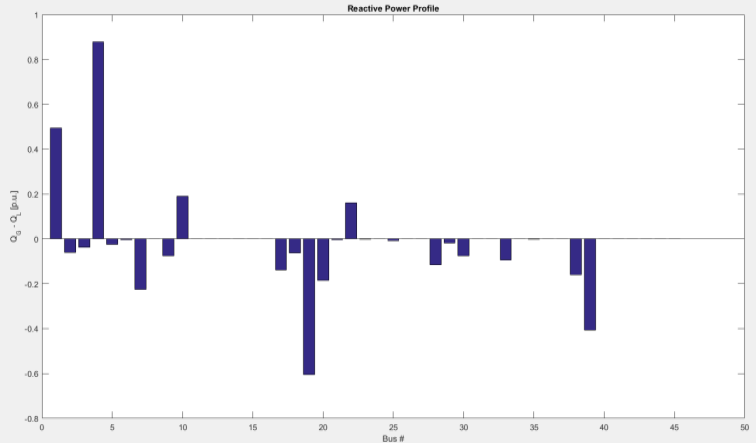
Figure 17. Reactive Power Flow Curve of the Network (Scenario 1).
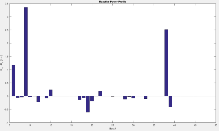
Figure 18. Reactive Power Flow Curve (Scenario 2).
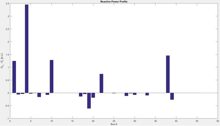
Figure 19. Reactive Power Flow Curve (Scenario 3).
Information


