This article presents the results of a study on improving surface quality during the mechanical machining of complex-shaped sections of metal mold components manufactured for the production of plastic products by injection molding. In the conventional milling method, narrow guide grooves (2.9 mm in width, 2.0 mm in depth) require machining with small-diameter end mills (D=2.5 mm). Such cutters have low stiffness, are prone to vibration, wear quickly, and degrade the surface quality. The study proposes a technology in which the difficult-to-machine section is manufactured as a separate part and installed into a seat formed in the main mold component by means of an interference fit. This approach eliminates the need for special fixtures and enables the use of larger-diameter (D=12 mm) rigid end mills. Experimental investigations were conducted on 40X structural alloy steel, comparing conventional milling with the proposed separate part technology. A power-regression mathematical model relating surface roughness to the main cutting parameters (cutting speed and feed per tooth) was developed and validated against experimental data. The results showed that surface roughness improved by 45.8% (from Ra=1.42 to Ra=0.77 μm), machining time decreased by 18.4%, and tool stiffness increased by a factor of 179. The proposed technology was implemented at the Navoi Machine-Building Plant, confirming its practical effectiveness.
| Published in | American Journal of Mechanics and Applications (Volume 13, Issue 2) |
| DOI | 10.11648/j.ajma.20261302.11 |
| Page(s) | 22-27 |
| Creative Commons |
This is an Open Access article, distributed under the terms of the Creative Commons Attribution 4.0 International License (http://creativecommons.org/licenses/by/4.0/), which permits unrestricted use, distribution and reproduction in any medium or format, provided the original work is properly cited. |
| Copyright |
Copyright © The Author(s), 2026. Published by Science Publishing Group |
Chain Drive, Distance Between Axles, Chain Network, Length, Vector, Contour, Angle, Equation
Property | Value | Unit |
|---|---|---|
Hardness (as delivered) | 269–302 | HB |
Hardness (after hardening) | 48–56 | HRC |
Tensile strength | 980 | MPa |
Yield strength | 785 | MPa |
Thermal expansion coefficient | 11.9 × 10⁻⁶ | 1/°C |
Parameter | Conventional | Separate part | Seat milling |
|---|---|---|---|
Cutter diameter D, mm | 2.5 | 12 | 20 |
Number of teeth z | 2 | 4 | 4 |
Cutting speed V, m/min | 23.6 | 75.4 | 125.6 |
Feed per tooth sz, mm/tooth | 0.008 | 0.05 | 0.08 |
Cutting depth t, mm | 0.3 | 1.0 | 1.5 |
Tool material | VK8 | VK8 | VK8 |
Configuration | Pz static, N | Kdin | Pz dynamic, N | Ra, μm |
|---|---|---|---|---|
Conventional (D=2.5) | 2.4 | 2.0 | 5.8 | 1.42 |
Separate part (D=12) | 26.6 | 1.1 | 29.3 | 0.77 |
Seat milling (D=20) | 58.8 | 1.15 | 67.6 | — |
Cutter | D, mm | I, mm⁴ | j, N/mm | Relative stiffness |
|---|---|---|---|---|
Conventional | 2.5 | 1.92 | 449 | 1× (reference) |
Separate part | 12 | 1018 | 80 168 | 179× |
Seat milling | 20 | 7854 | 316 673 | 705× |
E | Elastic Modulus of the Tool Material |
| [1] | Menges, G., Michaeli, W., Mohren, P. How to Make Injection Molds. 3rd ed. Munich: Hanser Publishers, 2001. 612 p. |
| [2] | Mennig, G., Stoeckhert, K. Mold-Making Handbook. 3rd ed. Munich: Hanser Publishers, 2013. 700 p. |
| [3] | Gologlu, C., Sakarya, N. The effects of cutter path strategies on surface roughness of pocket milling of 1.2738 steel. Journal of Materials Processing Technology, 2008, vol. 206, pp. 7–15. |
| [4] | Kara, F., Öztürk, B. Comparison and optimization of PVD and CVD method on surface roughness and flank wear in hard-machining. Sensor Review, 2019, vol. 39, no. 1, pp. 24–33. |
| [5] | Ribeiro, J., Lopes, H., Queijo, L., Figueiredo, D. Optimization of cutting parameters to minimize the surface roughness in the end milling process. Measurement, 2017, vol. 102, pp. 49–56. |
| [6] | Kosilova, A. G., Meshcheryakov, R. K. Handbook of a Machine-Building Technologist. Vol. 2. Moscow: Mashinostroyeniye, 1985. 496 p. |
| [7] | GOST R 71717-2024. Solid carbide end mills. Dimensions. Specifications. Moscow: Russian Institute of Standardization, 2024. 13 p. |
| [8] | Boothroyd, G., Knight, W. A. Fundamentals of Machining and Machine Tools. 3rd ed. Boca Raton: CRC Press, 2006. 573 p. |
| [9] | Davim, J. P. Machining of Hard Materials. London: Springer-Verlag, 2011. 211 p. |
| [10] | Trent, E. M., Wright, P. K. Metal Cutting. 4th ed. Boston: Butterworth-Heinemann, 2000. 446 p. |
| [11] | Benardos, P. G., Vosniakos, G. C. Predicting surface roughness in machining: a review. International Journal of Machine Tools and Manufacture, 2003, vol. 43, no. 8, pp. 833–844. |
| [12] | Quintana, G., Ciurana, J. Chatter in machining processes: A review. International Journal of Machine Tools and Manufacture, 2011, vol. 51, no. 5, pp. 363–376. |
| [13] | Altintas, Y. Manufacturing Automation: Metal Cutting Mechanics, Machine Tool Vibrations, and CNC Design. 2nd ed. Cambridge: Cambridge University Press, 2012. 366 p. |
| [14] | Grzesik, W. Advanced Machining Processes of Metallic Materials: Theory, Modelling and Applications. 2nd ed. Amsterdam: Elsevier, 2017. 608 p. |
| [15] | Childs, T., Maekawa, K., Obikawa, T., Yamane, Y. Metal Machining: Theory and Applications. London: Arnold, 2000. 408 p. |
APA Style
Ogli, A. D. A., Yuldashalievich, X. Y. (2026). Theoretical Determination of Changes in Chain Networks Lengths. American Journal of Mechanics and Applications, 13(2), 22-27. https://doi.org/10.11648/j.ajma.20261302.11
ACS Style
Ogli, A. D. A.; Yuldashalievich, X. Y. Theoretical Determination of Changes in Chain Networks Lengths. Am. J. Mech. Appl. 2026, 13(2), 22-27. doi: 10.11648/j.ajma.20261302.11
@article{10.11648/j.ajma.20261302.11,
  author = {Akbarov Dostonbek Axmadali Ogli and Xusanov Yunusali Yuldashalievich},
  title = {Theoretical Determination of Changes in Chain Networks Lengths},
  journal = {American Journal of Mechanics and Applications},
  volume = {13},
  number = {2},
  pages = {22-27},
  doi = {10.11648/j.ajma.20261302.11},
  url = {https://doi.org/10.11648/j.ajma.20261302.11},
  eprint = {https://article.sciencepublishinggroup.com/pdf/10.11648.j.ajma.20261302.11},
  abstract = {This article presents the results of a study on improving surface quality during the mechanical machining of complex-shaped sections of metal mold components manufactured for the production of plastic products by injection molding. In the conventional milling method, narrow guide grooves (2.9 mm in width, 2.0 mm in depth) require machining with small-diameter end mills (D=2.5 mm). Such cutters have low stiffness, are prone to vibration, wear quickly, and degrade the surface quality. The study proposes a technology in which the difficult-to-machine section is manufactured as a separate part and installed into a seat formed in the main mold component by means of an interference fit. This approach eliminates the need for special fixtures and enables the use of larger-diameter (D=12 mm) rigid end mills. Experimental investigations were conducted on 40X structural alloy steel, comparing conventional milling with the proposed separate part technology. A power-regression mathematical model relating surface roughness to the main cutting parameters (cutting speed and feed per tooth) was developed and validated against experimental data. The results showed that surface roughness improved by 45.8% (from Ra=1.42 to Ra=0.77 μm), machining time decreased by 18.4%, and tool stiffness increased by a factor of 179. The proposed technology was implemented at the Navoi Machine-Building Plant, confirming its practical effectiveness.},
 year = {2026}
}
TY  - JOUR
T1  - Theoretical Determination of Changes in Chain Networks Lengths
AU  - Akbarov Dostonbek Axmadali Ogli
AU  - Xusanov Yunusali Yuldashalievich
Y1  - 2026/06/26
PY  - 2026
N1  - https://doi.org/10.11648/j.ajma.20261302.11
DO  - 10.11648/j.ajma.20261302.11
T2  - American Journal of Mechanics and Applications
JF  - American Journal of Mechanics and Applications
JO  - American Journal of Mechanics and Applications
SP  - 22
EP  - 27
PB  - Science Publishing Group
SN  - 2376-6131
UR  - https://doi.org/10.11648/j.ajma.20261302.11
AB  - This article presents the results of a study on improving surface quality during the mechanical machining of complex-shaped sections of metal mold components manufactured for the production of plastic products by injection molding. In the conventional milling method, narrow guide grooves (2.9 mm in width, 2.0 mm in depth) require machining with small-diameter end mills (D=2.5 mm). Such cutters have low stiffness, are prone to vibration, wear quickly, and degrade the surface quality. The study proposes a technology in which the difficult-to-machine section is manufactured as a separate part and installed into a seat formed in the main mold component by means of an interference fit. This approach eliminates the need for special fixtures and enables the use of larger-diameter (D=12 mm) rigid end mills. Experimental investigations were conducted on 40X structural alloy steel, comparing conventional milling with the proposed separate part technology. A power-regression mathematical model relating surface roughness to the main cutting parameters (cutting speed and feed per tooth) was developed and validated against experimental data. The results showed that surface roughness improved by 45.8% (from Ra=1.42 to Ra=0.77 μm), machining time decreased by 18.4%, and tool stiffness increased by a factor of 179. The proposed technology was implemented at the Navoi Machine-Building Plant, confirming its practical effectiveness.
VL  - 13
IS  - 2
ER  -
Department of Mechanical Engineering Technology, Fergana State Technical University, Fergana, Uzbekistan
Biography: Akbarov Dostonbek Axmadali Ogli graduated from Fergana Polytechnic Institute in 2021 and completed his master's degree in Mechanical Engineering Technology and Equipment (in manufacturing) in 2023. In 2025, he enrolled as a doctoral candidate (PhD) at the Department of Mechanical Engineering Technology, Fergana State Technical University, Uzbekistan. His research focuses on improving the efficiency of mechanical machining technology for mold components, particularly the development of separate part technology for machining complex-shaped sections. He has authored 13 scientific articles and conference papers.
Research Fields: Mold component milling technology, separate part technology, cutting force and stiffness analysis, surface roughness mathematical modeling, 40X steel machining.

Department of Applied Mechanics, Fergana State Technical University, Fergana, Uzbekistan
Biography: Xusanov Yunusali Yuldashalievich is a Doctor of Technical Sciences (DSc), Associate Professor, and Head of the Department of Applied Mechanics at Fergana State Technical University, Uzbekistan. His research interests include machining technology, cutting processes, machine tools, and manufacturing optimization. He serves as a scientific supervisor for doctoral candidates and has authored numerous scientific publications in the field of mechanical engineering.
Research Fields: Machining technology, cutting processes, machine tools and equipment, manufacturing optimization, tool wear analysis.

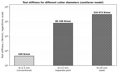
Figure 1. Tool stiffness for different cutter diameters (logarithmic scale, cantilever model).
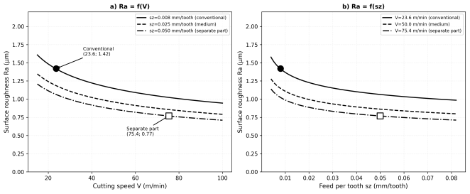
Figure 2. Dependence of surface roughness Ra on cutting parameters: a) on cutting speed V; b) on feed per tooth sz (40X steel, mathematical model).
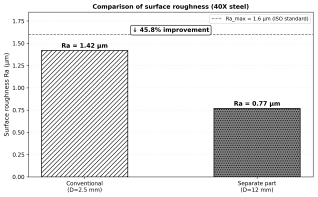
Figure 3. Comparison of surface roughness between conventional and separate part technology (40X steel).
Information

