The Stretched-Wire Alignment Technique (SWAT) is one method of magnet alignment for linear induction accelerators. The applications of SWAT have been implemented for aligning solenoid magnets on the Scorpius linear induction accelerator which will be sited at the Nevada National Security Site and the Flash X-Ray (FXR) linear induction accelerator at Lawrence Livermore National Laboratory’s Contained Firing Facility. This article describes both systematic (repeatable) and random sources of background and noise as well as practical ways to eliminate or reduce them to acceptable levels. Systematic sources include reflections from wire ends, rapid sag due to ohmic heating of the wire, magnetic materials, and shot rate. Random sources include air currents, vibration of nearby equipment, mechanical stability of test equipment, and the instruments used to measure the wire motion. Mitigations include curve fitting and adaptive noise signal cancellation, and mechanical damping. Finite Element Analysis (FEA) was used to identify and resolve a repeatable wire vibration frequency interfering with the signal resolution. Two stretched wire alignment technique set ups from Sandia National Labs and Lawrence Livermore National Lab have shown background noise sources and ways of mitigating them by either analysis methods or change of mechanical configuration. Conclusions that were drawn included the severe sensitivity of the deflection to even small external interferences of the SWAT wire such that it requires attention to detail in mechanical set up and analysis.
This is an Open Access article, distributed under the terms of the Creative Commons Attribution 4.0 International License (http://creativecommons.org/licenses/by/4.0/), which permits unrestricted use, distribution and reproduction in any medium or format, provided the original work is properly cited.
SWAT (Stretched-wire Alignment Technique), Linear Inductive Accelerator, Noise Cancellation
1. Introduction
The Stretched Wire Alignment Technique (SWAT), or the pulsed wire technique, originally introduced by Warren in 1988
[1]
R. W. Warren, “Limitations on the use of the pulsed-wire field measuring technique,” Nucl. Instrum. Methods in Phys. Res. A, vol. 272, pp. 257-263, 1988,
, is a diagnostic method for charactering magnetic fields, particularly in undulators. The method involves tensioning a thin wire along the axis of the undulator and sending a short electrical current pulse through it. As the pulse interacts with the local magnetic field, Lorentz forces are generated, producing a mechanical (acoustic) wave that propagates along the wire. The resulting transverse displacement of the wire, which is measured by optical sensors (laser micrometer) positioned outside the magnetic field region, provides information about the integrated magnetic field.
Depending on the width of the current pulse, the observed wire displacement is proportional to the integral of the magnetic field, making the technique suitable for precise field mapping and alignment verification. Since its inception, numerous enhancements have significantly improved the accuracy, resolution, and applicability of the pulsed wire method
[2]
O. Shahal, B. V. Elkonin and J. S. Sokolowski, “Dispersion interference in the pulsed-wire measurement method,” Nucl. Inst. Methods Phys. Res. A, vol 296 588-91, 1990,
D. W. Preston and R. W. Warren, “Wiggler field measurements and corrections using the pulsed wire technique,” Nucl. Inst. Methods Phys. Res. A 318 794-7, 1992,
M. Fabrice, C. Muriel, F. Christian and M. Olivier, “Improvements of the pulsed-wire method to measure undulators,” IEEE Trans. on Applied Superconductivity 10 pp. 1443-6, 2000,
D. Arbelaez, T. Wilks, A. Madur, S. Prestemon, S. Marks and R. Schlueter, “A dispersion and pulse width correction algorithm for the pulsed wire method,” Nucl. Inst. Methods Phys. Res. A, 716 62-70, 2013,
M. Vall´eau, C. Benabderahmane, M. E. Couprie, O. Marcouill´e, F. Marteau and J. V´et´eran, “Measurements of SOLEIL insertion devices using pulsed wire method,” Proc. 2nd Int. Particle Accelerator Conf. (IPAC’11), San Sebastian, Spain pp. 3242-44, Sep. 2011.
[7]
M. Kasa M, “DSP methods for correcting dispersion and pulse width effects during pulsed wire measurements,” Measurement, 122 224-31, 2018,
R. Teyber, E. Wallen, D. Arbelaez, and S. Prestemon, “Combined Function Magnetic Measurement Syste,” IEEE Transactions on Applied Superconductivity, vol. 30, no. 4, June 2020,
Furthermore, a combined-function magnetic measurement system is developed that couples the functionality of rotating coils with pulsed wire measurements to improve measurement efficiency
[9]
A. A. Varfolomeev, et al., “Improved wire deflection method for magnetic field measurements in long undulators,” Nucl. Instrum. Methods in Phys. Res. A, vol. 359, pp. 93-96, 1995,
V. Teotia and S. Malhotra, “Single Stretch Wire and Vibrating wire measurement system for characterization of multipole accelerator magnets,” Journal of Instrumentation, vol. 18, P07029, 2023.
One SWAT system is applied to measure a magnet’s magnetic axis and compare it to mechanical axis at Sandia National Labs (SNL) and Lawrence Livermore National Lab (LLNL). This is useful while aligning accelerator magnet components to ensure alignment of the magnetic fields. A collaboration between SNL, LLNL, and Nevada National Security Sites (NNSS) was developed to identify, analyze, and mitigate various noise sources in two separate SWAT systems. The two systems encountered noise sources which were common between the two and others that were specific to each labs’ SWAT system’s configurations and methods. This paper summarizes some of the key take aways from this collaboration.
First, the basic concepts of SWAT are reviewed followed by a description of the two SWAT setups studied for this collaboration. A review of the systematic and random sources of background and noises are then described followed by a discussion of mitigation strategy.
2. Basic Concepts
The main goal of the SWAT method is to measure the magnetic axis and the mechanical axis of an electromagnet and compare the difference
[11]
M. Bates, A. Warrick, M. Mitchell, T. Thornton, A. Fetterman, and J. Ma, “Statistical Uncertainty Studies on Various Data Analysis Methods for Stretched Wire Alignment Technology (SWAT) used for the Scorpius Injector”, International Particle Accelerator Conference (IPAC’25), June 1-6, 2026.
[11]
. The method uses a thin conductive wire under tension through the magnet under test
[8]
R. Teyber, E. Wallen, D. Arbelaez, and S. Prestemon, “Combined Function Magnetic Measurement Syste,” IEEE Transactions on Applied Superconductivity, vol. 30, no. 4, June 2020,
. SNL and LLNL each test solenoid magnets that have different geometries. When a current is pulsed through the wire, the wire undergoes a Lorentz mechanical force causing the wire to physically move according to the magnetic field it is experiencing at that point in 4D phase space (x, x’, y, y’)
[12]
W. D. Stem “Scorpius Injector Solenoid Magnet Alignment Characterization,” LLNL-TR-842413, November 2020.
. These movements are measured and can be analyzed to inform how far away the wire is from the magnetic axis. While the methods of how each lab analyzes the acquired data are beyond the scope of this summary, we just comment that SNL SWAT uses a grid region with peak-to-peak measurement analysis and LLNL uses a linear basis-function mapping approach.
A complete misalignment between the mechanical and magnetic axes introduces four degrees of freedom for describing the magnetic axis’ position relative to the mechanical axis. This can be described using Cartesian coordinates (x and y projections), where an offset and tilt are quoted for each projection.
3. Description of Systems
The two SWAT systems (Scorpius and FXR) have similar basic SWAT set ups but are also measuring two very different solenoid magnet shapes and sizes. Beryllium copper (BeCu, a copper alloy with 0.5-3% beryllium) wire is used at FXR SWAT system and pure copper wire is used at Scorpius SWAT system. The extent of the shapes and sizes of solenoid are described in Table 1.
Because the required accuracy of each SWAT system is to report the center of the magnetic axis offset and tilt to within 0.2 mm and 0.2 mrad, it is important to account for sources of background noise in the measurements. Each source could be categorized and described as either systematic or random in nature. These next two sections include some details of the findings found on each of the identified background or noise sources.
Table 1. Solenoid and SWAT specifications for SNL & LLNL configurations and set ups.
Solenoid Parameters
Scorpius Solenoid
FXR Solenoid
Solenoid Radius
254 mm
105 mm
Solenoid Length
50 mm
450 mm
Wire Length
~2 m
2 m
Wire Diameter
127 m
101.6 m
Tension Mass
0.25 kg
0.35-0.45 kg
Pulse Current
18 Amps
3 Amps
Pulse Width
0.1 ms
0.3 ms
4. Systematic Noises
4.1. Wire End Reflections
Because the wire ends are fixed on both ends and there was limited damping of the oscillations of the wire, the boundary conditions of the mechanical wave made it such that it would be difficult to interpret the mechanical deflections after the waves reflected. Effort was made therefore to make it such that the position of the sensors and the solenoid were able to make a full measurement before the reflection contaminated the measurement.
4.2. Magnetic Material Interference
Another discovery was the interference of magnetic material near the SWAT measurements. Examples include magnetic mounts for Spherically Mounted Retroreflectors (SMR’s), magnetic linear stages distorting the solenoid magnetic field and unexpected magnetized tension posts.
The SMR’s are used to position the fine wire from local coordinate space to global coordinates for positioning. Luckily this was dealt with twofold: first, with a background measurement, the interference on the waveform was accounted for by subtracting it from a second measurement with the solenoid on. Second, the magnetic SMR mounts were built with removable permanent magnets, making them trivial to reduce the noise.
Another interference was that the linear stages used had steel casings which absorbed some of the magnetic field flux near the measurement wire. This caused distortions of the measurement even after subtracting the background. It was concluded that moving the linear stage farther from the wire with an extension arm was the best solution. This mitigated the issue and was integrated into the setup.
Yet another surprising source of magnetic material interference was finding that the tensioning rods used in the LLNL SWAT were magnetized. This was easily shown by demagnetizing them.
4.3. Shot Rate
There was also concern that having pulses too close in time between each other would result in further noise effects that would cause data to be either rejected or redone. Measurements were taken with a scope to measure the deflection of the wire with a strong permanent magnet, simulating the largest possible deflection for the SWAT. A fitted exponential decay constant , was close to 1.2 seconds. From this it was concluded that a wait time of 4 seconds would satisfy the 3 rule of thumb.
4.4. Ohmic Heating of Wire
Ohmic heating of the wire occurs immediately following the application of the kicking pulse. Due to the relative large current passing through the wire - despite the short duration - the wire experiences a temperature rise, resulting in a temporary loss of tension. This loss of tension induces vertical oscillation increasing of the wire. Figure 1 illustrates the vertical deflections of the wire under varying pulse amplitudes (in amperes) and pulse durations (in milliseconds). Although the product of current and pulse duration () remains nearly constant across all cases, the average vertical deflection amplitudes differ significantly. This variation confirms the presence of Ohmic heating, as the energy deposited in the wire scales with the square of the current.
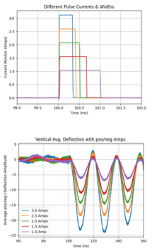
Figure 1. Demonstration of Wire Sag with different Pulse widths. Top includes a zoom in on the driving current pulse with bottom showing the vertical deflection.
5. Random Noises
5.1. Air Currents
Other noises did not happen repeatably. One example of this is the sensitive measurements for the wire movement would see the wire wave in the air currents about 1.3 while both our measuring devices could resolve 0.1 , or better. It is worth noting that this movement also had a sinusoidal shape trend to it with the stretched wires fundamental resonant frequency, which was different for each SWAT set up. With this nonstationary noise some post processing of the deflections was used to quantify the uncertainty in the actual wire deflection.
5.2. Environment Noises
Some other signal noise was environment based, from loud water coolers or air compressors. The sensitivity was such that a truck unloading material across the street clearly created outlier data waveforms in a sample set. Even how near the operator stood near the table contributed to the measurable noise. We were only able to minimize some of these noises.
5.3. Mechanical Stability
Another systematic noise that was discovered and corrected was a resonant frequency that was caused from resonance frequencies in the wire holding arms in the SNL SWAT configuration. It was observed during experiments that a background signal with frequency ranging from 105-130 Hz occasionally appeared. The strength of this signal was often dominant compared to the true signal. In these cases, the true signal would be polluted. The spectrum of signal with noise and background was identified using an FFT. The range of 105-130 Hz was subtracted from the measurement using a band stop filter, and the result was converted back to the time domain. Noise overlapping with the true signal could not be filtered out using this method so physical changes were made to the SNL SWAT system in an effort to isolate the true signal when clear frequencies couldn’t be removed.
The wire holder arm was examined in isolation using a modal analysis to identify its vibration modes as a potential source. Modal analysis performed using ANSYS FEA
[13]
N. Kukreja, and P. Singhal, “Design and verify a natural frequency using ANSYS Software,” Materials Today Proceedings, VOL. 45, Part 2, 3255-3258, 2021.
showed peaks around 23 Hz, 155 Hz, and 215 Hz. A fin structure was fitted to the arm to stiffen the wire holder as shown in Figure 2. Subsequent testing showed removal of the pre pulse 166 Hz frequency and mitigation of the other two signals.
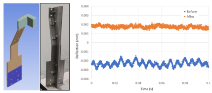
Figure 2. Mechanical design before (top left) and after (top right). Modifications resulted in significant noise reduction in wire deflections shown in before and after waveforms. Subsequent testing showed removal of the pre pulse 166 Hz frequency and mitigation of the other two signals.
6. Analysis Mitigations
A mitigation method considered during the collaboration was to take multiple current pulse measurements while in the same position. This determined an uncertainty floor and envelope for the average. This was ultimately the basis of the LLNL SWAT methodology for post processing. SNAL SWAT has explored using a moving average technique as well as taking multiple shots.
Because the nature of the noise and the signals were sometimes of the same frequency this prevented frequency bandpass filters from being used in processing data. Use of Cubic splines was also investigated, but it was ultimately concluded that higher frequency signals would likely be lost.
There was also an effort to use a droplet of oil for dampening the wire air vibrations. This proved to be difficult with the necessary range of motion and results are improved in most of the scanning range.
7. Conclusions
Two stretched wire alignment technique set ups from Sandia National Labs and Lawrence Livermore National Lab have shown background noise sources and ways of mitigating them by either analysis methods or change of mechanical configuration.
In subsequent investigations, the repeatability of the nominal offset measurement was determined to be approximately 0.2 mm in the vertical (y) direction and less than 0.1 mm in the horizontal (x) direction. These results are consistent with the initial design specification outlined in Reference
[12]
W. D. Stem “Scorpius Injector Solenoid Magnet Alignment Characterization,” LLNL-TR-842413, November 2020.
. A detailed uncertainty analysis will be presented by the authors at the IPAC’25 conference in June 2025.
Conclusions that were drawn included the severe sensitivity of the deflection to even small external interferences of the SWAT wire such that it requires attention to detail in mechanical set up and analysis.
Abbreviations
SWAT
Stretched-wire Alignment Technique
FXR
Flash X-Ray
FEA
Finite Element Analysis
SNL
Sandia National Laboratories
LLNL
Lawrence Livermore National Laboratory
NNSS
Nevada National Security Sites
SMR
Spherically Mounted Retroreflectors
FFT
Fast Fourier Transfer
Acknowledgments
Authors would like to thank to the support of Advanced Sources and Detectors (ASD) project.
Additionally, we acknowledge engineering support from Evan Misak (Los Alamos National Laboratory).
Author Contributions
Michael Bates: conceptualization, experimental investigation, FEA simulation, analysis, writing.
Jian Ma: is the corresponding author and contributes to conceptualization, experimental investigation, analysis, writing review and editing.
Marc Mitchell: Technical discussion.
Charles Melton: Technical discussion.
Patrick Corcoran: Technical discussion.
William Stem: Technical discussion.
Sean Sheehan: Experiment Investigation.
Data Availability Statement
The data is available from the corresponding author upon reasonable request.
Funding
Sandia National Laboratories is a multimission laboratory managed and operated by National Technology & Engineering Solutions of Sandia, LLC, a wholly owned subsidiary of Honeywell International Inc., for the U. S. Department of Energy’s National Nuclear Security Administration under contract DE-NA0003525. This paper describes objective technical results and analysis. Any subjective views or opinions that might be expressed in the paper do not necessarily represent the views of the U. S. Department of Energy or the United States Government.
Conflicts of Interest
The authors declare no conflicts of interest.
References
[1]
R. W. Warren, “Limitations on the use of the pulsed-wire field measuring technique,” Nucl. Instrum. Methods in Phys. Res. A, vol. 272, pp. 257-263, 1988,
O. Shahal, B. V. Elkonin and J. S. Sokolowski, “Dispersion interference in the pulsed-wire measurement method,” Nucl. Inst. Methods Phys. Res. A, vol 296 588-91, 1990,
D. W. Preston and R. W. Warren, “Wiggler field measurements and corrections using the pulsed wire technique,” Nucl. Inst. Methods Phys. Res. A 318 794-7, 1992,
M. Fabrice, C. Muriel, F. Christian and M. Olivier, “Improvements of the pulsed-wire method to measure undulators,” IEEE Trans. on Applied Superconductivity 10 pp. 1443-6, 2000,
D. Arbelaez, T. Wilks, A. Madur, S. Prestemon, S. Marks and R. Schlueter, “A dispersion and pulse width correction algorithm for the pulsed wire method,” Nucl. Inst. Methods Phys. Res. A, 716 62-70, 2013,
M. Vall´eau, C. Benabderahmane, M. E. Couprie, O. Marcouill´e, F. Marteau and J. V´et´eran, “Measurements of SOLEIL insertion devices using pulsed wire method,” Proc. 2nd Int. Particle Accelerator Conf. (IPAC’11), San Sebastian, Spain pp. 3242-44, Sep. 2011.
[7]
M. Kasa M, “DSP methods for correcting dispersion and pulse width effects during pulsed wire measurements,” Measurement, 122 224-31, 2018,
R. Teyber, E. Wallen, D. Arbelaez, and S. Prestemon, “Combined Function Magnetic Measurement Syste,” IEEE Transactions on Applied Superconductivity, vol. 30, no. 4, June 2020,
A. A. Varfolomeev, et al., “Improved wire deflection method for magnetic field measurements in long undulators,” Nucl. Instrum. Methods in Phys. Res. A, vol. 359, pp. 93-96, 1995,
V. Teotia and S. Malhotra, “Single Stretch Wire and Vibrating wire measurement system for characterization of multipole accelerator magnets,” Journal of Instrumentation, vol. 18, P07029, 2023.
M. Bates, A. Warrick, M. Mitchell, T. Thornton, A. Fetterman, and J. Ma, “Statistical Uncertainty Studies on Various Data Analysis Methods for Stretched Wire Alignment Technology (SWAT) used for the Scorpius Injector”, International Particle Accelerator Conference (IPAC’25), June 1-6, 2026.
[12]
W. D. Stem “Scorpius Injector Solenoid Magnet Alignment Characterization,” LLNL-TR-842413, November 2020.
N. Kukreja, and P. Singhal, “Design and verify a natural frequency using ANSYS Software,” Materials Today Proceedings, VOL. 45, Part 2, 3255-3258, 2021.
Bates, M., Fetterman, A., Mitchell, M., Melton, C., Corcoran, P., et al. (2025). Analysis Background & Noise in Stretched Wire Alignment Technique Measurements. American Journal of Modern Physics, 14(4), 194-199. https://doi.org/10.11648/j.ajmp.20251404.13
Bates M, Fetterman A, Mitchell M, Melton C, Corcoran P, et al. Analysis Background & Noise in Stretched Wire Alignment Technique Measurements. Am J Mod Phys. 2025;14(4):194-199. doi: 10.11648/j.ajmp.20251404.13
@article{10.11648/j.ajmp.20251404.13,
author = {Michael Bates and Aaron Fetterman and Marc Mitchell and Charles Melton and Patrick Corcoran and William Stem and Sean Sheehan and Darryl Droemer and Jian Ma},
title = {Analysis Background & Noise in Stretched Wire Alignment Technique Measurements
},
journal = {American Journal of Modern Physics},
volume = {14},
number = {4},
pages = {194-199},
doi = {10.11648/j.ajmp.20251404.13},
url = {https://doi.org/10.11648/j.ajmp.20251404.13},
eprint = {https://article.sciencepublishinggroup.com/pdf/10.11648.j.ajmp.20251404.13},
abstract = {The Stretched-Wire Alignment Technique (SWAT) is one method of magnet alignment for linear induction accelerators. The applications of SWAT have been implemented for aligning solenoid magnets on the Scorpius linear induction accelerator which will be sited at the Nevada National Security Site and the Flash X-Ray (FXR) linear induction accelerator at Lawrence Livermore National Laboratory’s Contained Firing Facility. This article describes both systematic (repeatable) and random sources of background and noise as well as practical ways to eliminate or reduce them to acceptable levels. Systematic sources include reflections from wire ends, rapid sag due to ohmic heating of the wire, magnetic materials, and shot rate. Random sources include air currents, vibration of nearby equipment, mechanical stability of test equipment, and the instruments used to measure the wire motion. Mitigations include curve fitting and adaptive noise signal cancellation, and mechanical damping. Finite Element Analysis (FEA) was used to identify and resolve a repeatable wire vibration frequency interfering with the signal resolution. Two stretched wire alignment technique set ups from Sandia National Labs and Lawrence Livermore National Lab have shown background noise sources and ways of mitigating them by either analysis methods or change of mechanical configuration. Conclusions that were drawn included the severe sensitivity of the deflection to even small external interferences of the SWAT wire such that it requires attention to detail in mechanical set up and analysis.},
year = {2025}
}
TY - JOUR
T1 - Analysis Background & Noise in Stretched Wire Alignment Technique Measurements
AU - Michael Bates
AU - Aaron Fetterman
AU - Marc Mitchell
AU - Charles Melton
AU - Patrick Corcoran
AU - William Stem
AU - Sean Sheehan
AU - Darryl Droemer
AU - Jian Ma
Y1 - 2025/07/28
PY - 2025
N1 - https://doi.org/10.11648/j.ajmp.20251404.13
DO - 10.11648/j.ajmp.20251404.13
T2 - American Journal of Modern Physics
JF - American Journal of Modern Physics
JO - American Journal of Modern Physics
SP - 194
EP - 199
PB - Science Publishing Group
SN - 2326-8891
UR - https://doi.org/10.11648/j.ajmp.20251404.13
AB - The Stretched-Wire Alignment Technique (SWAT) is one method of magnet alignment for linear induction accelerators. The applications of SWAT have been implemented for aligning solenoid magnets on the Scorpius linear induction accelerator which will be sited at the Nevada National Security Site and the Flash X-Ray (FXR) linear induction accelerator at Lawrence Livermore National Laboratory’s Contained Firing Facility. This article describes both systematic (repeatable) and random sources of background and noise as well as practical ways to eliminate or reduce them to acceptable levels. Systematic sources include reflections from wire ends, rapid sag due to ohmic heating of the wire, magnetic materials, and shot rate. Random sources include air currents, vibration of nearby equipment, mechanical stability of test equipment, and the instruments used to measure the wire motion. Mitigations include curve fitting and adaptive noise signal cancellation, and mechanical damping. Finite Element Analysis (FEA) was used to identify and resolve a repeatable wire vibration frequency interfering with the signal resolution. Two stretched wire alignment technique set ups from Sandia National Labs and Lawrence Livermore National Lab have shown background noise sources and ways of mitigating them by either analysis methods or change of mechanical configuration. Conclusions that were drawn included the severe sensitivity of the deflection to even small external interferences of the SWAT wire such that it requires attention to detail in mechanical set up and analysis.
VL - 14
IS - 4
ER -
Pulse Power Engineering Department, Sandia National Laboratory, Albuquerque, the United States
Biography:
Michael Bates is a mechanical engineer at Sandia National Laboratories in the Pulsed Power Sciences Center. He has Bachelor of Science degrees in mechanical and aerospace engineering which he received from the University of Florida in 2022. He worked in an experimental physics lab at UF studying high-temperature superconductors and other novel materials under Dr. James Hamlin. At SNL, he has worked in SWAT optimization and testing for the Scorpius project and in various other roles in the pulsed power sciences center. He has participated in the Advanced Physical Society March Meeting for condensed matter research and the 2024 International Particle Accelerator Conference.
Research Fields:
pulse power and linear particle accelerator
Accelerator Development Group, Lawrence Livermore National Laboratory, Livermore, the United States
Biography:
Aaron Fetterman is an Applied Physicist and Engineer specializing in accelerator systems at Lawrence Livermore National Laboratory (LLNL). He holds a Master’s degree in Applied Physics from Northern Illinois University, where his research focused on eigen-emittance measurements in angular momentum-dominated beams for next-generation Electron Ion Collider designs. At LLNL, Aaron has served as lead operations physicist for Scorpius pulsed power devices and has developed advanced diagnostic tools for beam alignment and position monitoring. His work emphasizes experimental research, using innovative analysis methods to analyze and enhance accelerator performance and collaborates with scientists and engineers to address challenges in accelerator systems. With a passion for advancing accelerator technology he works to drive impactful research and development in the field.
Accelerator Development Group, Lawrence Livermore National Laboratory, Livermore, the United States
Biography:
William Stem is a staff scientist at Lawrence Livermore National Laboratory in the Engineering Department. He completed his PhD in Physics from University of Maryland, College Park in 2015, with an emphasis on diagnostics for particle accelerators. He continued that emphasis with a postdoc at GSI in Darmstadt, Germany before joining LLNL in 2018. Dr. Stem currently serves as LLNL’s technical liaison to NA-113 at NNSA headquarters in Washington, D. C. Before this role, he served as the Work Package Manager for the injector magnets and beam physics for the Scorpius project and technical SME for Accelerator Operations at LLNL.
Enhanced Capabilities for Subcritical Experiments Division, Nevada National Security Sites, North Las Vegas, the United States
Jian Ma
Enhanced Capabilities for Subcritical Experiments Division, Nevada National Security Sites, North Las Vegas, the United States
Biography:
Jian Ma is a senior principal scientist at Nevada National Security Sites (NNSS), Department of Enhanced Capabilities for Subcritical Experiments (ECSE). He completed his PhD in Mechanical Engineering from Nanyang Technological University (NTU), Singapore in 2004, and his Master of Engineering in Fluid Mechanics from Fudan University, Shanghai, China in 1998. Dr. Ma holds a Professional Engineer license in Nevada state. He has participated in multiple collaboration projects in linear induction accelerator, nuclear energy and bio-energy. Before he joined NNSS, he was a research assistant professor in Mechanical Engineering Department, University of Nevada, Las Vegas (UNLV).
Bates, M., Fetterman, A., Mitchell, M., Melton, C., Corcoran, P., et al. (2025). Analysis Background & Noise in Stretched Wire Alignment Technique Measurements. American Journal of Modern Physics, 14(4), 194-199. https://doi.org/10.11648/j.ajmp.20251404.13
Bates M, Fetterman A, Mitchell M, Melton C, Corcoran P, et al. Analysis Background & Noise in Stretched Wire Alignment Technique Measurements. Am J Mod Phys. 2025;14(4):194-199. doi: 10.11648/j.ajmp.20251404.13
@article{10.11648/j.ajmp.20251404.13,
author = {Michael Bates and Aaron Fetterman and Marc Mitchell and Charles Melton and Patrick Corcoran and William Stem and Sean Sheehan and Darryl Droemer and Jian Ma},
title = {Analysis Background & Noise in Stretched Wire Alignment Technique Measurements
},
journal = {American Journal of Modern Physics},
volume = {14},
number = {4},
pages = {194-199},
doi = {10.11648/j.ajmp.20251404.13},
url = {https://doi.org/10.11648/j.ajmp.20251404.13},
eprint = {https://article.sciencepublishinggroup.com/pdf/10.11648.j.ajmp.20251404.13},
abstract = {The Stretched-Wire Alignment Technique (SWAT) is one method of magnet alignment for linear induction accelerators. The applications of SWAT have been implemented for aligning solenoid magnets on the Scorpius linear induction accelerator which will be sited at the Nevada National Security Site and the Flash X-Ray (FXR) linear induction accelerator at Lawrence Livermore National Laboratory’s Contained Firing Facility. This article describes both systematic (repeatable) and random sources of background and noise as well as practical ways to eliminate or reduce them to acceptable levels. Systematic sources include reflections from wire ends, rapid sag due to ohmic heating of the wire, magnetic materials, and shot rate. Random sources include air currents, vibration of nearby equipment, mechanical stability of test equipment, and the instruments used to measure the wire motion. Mitigations include curve fitting and adaptive noise signal cancellation, and mechanical damping. Finite Element Analysis (FEA) was used to identify and resolve a repeatable wire vibration frequency interfering with the signal resolution. Two stretched wire alignment technique set ups from Sandia National Labs and Lawrence Livermore National Lab have shown background noise sources and ways of mitigating them by either analysis methods or change of mechanical configuration. Conclusions that were drawn included the severe sensitivity of the deflection to even small external interferences of the SWAT wire such that it requires attention to detail in mechanical set up and analysis.},
year = {2025}
}
TY - JOUR
T1 - Analysis Background & Noise in Stretched Wire Alignment Technique Measurements
AU - Michael Bates
AU - Aaron Fetterman
AU - Marc Mitchell
AU - Charles Melton
AU - Patrick Corcoran
AU - William Stem
AU - Sean Sheehan
AU - Darryl Droemer
AU - Jian Ma
Y1 - 2025/07/28
PY - 2025
N1 - https://doi.org/10.11648/j.ajmp.20251404.13
DO - 10.11648/j.ajmp.20251404.13
T2 - American Journal of Modern Physics
JF - American Journal of Modern Physics
JO - American Journal of Modern Physics
SP - 194
EP - 199
PB - Science Publishing Group
SN - 2326-8891
UR - https://doi.org/10.11648/j.ajmp.20251404.13
AB - The Stretched-Wire Alignment Technique (SWAT) is one method of magnet alignment for linear induction accelerators. The applications of SWAT have been implemented for aligning solenoid magnets on the Scorpius linear induction accelerator which will be sited at the Nevada National Security Site and the Flash X-Ray (FXR) linear induction accelerator at Lawrence Livermore National Laboratory’s Contained Firing Facility. This article describes both systematic (repeatable) and random sources of background and noise as well as practical ways to eliminate or reduce them to acceptable levels. Systematic sources include reflections from wire ends, rapid sag due to ohmic heating of the wire, magnetic materials, and shot rate. Random sources include air currents, vibration of nearby equipment, mechanical stability of test equipment, and the instruments used to measure the wire motion. Mitigations include curve fitting and adaptive noise signal cancellation, and mechanical damping. Finite Element Analysis (FEA) was used to identify and resolve a repeatable wire vibration frequency interfering with the signal resolution. Two stretched wire alignment technique set ups from Sandia National Labs and Lawrence Livermore National Lab have shown background noise sources and ways of mitigating them by either analysis methods or change of mechanical configuration. Conclusions that were drawn included the severe sensitivity of the deflection to even small external interferences of the SWAT wire such that it requires attention to detail in mechanical set up and analysis.
VL - 14
IS - 4
ER -