Wire bonding attaches a fine wire from one connection pad to another, completing an electrical connection. Reduction-assisted immersion gold (RAIG) has recently gained popularity due to its ability to eliminate corrosion and plate thicker gold deposits. Implementing a RAIG process improves quality and reduces wire bonding product reliability risk. The purpose of this research was two-fold: 1) evaluate the effects of crossing two RAIG thicknesses against three wire bonding gram-forces on wire bond pull strength, and 2) evaluate two independent RAIG thickness effects on wire bond pull strength, all on an electroless nickel electroless palladium immersion gold (ENEPIG) final finished printed circuit board. A quantitative, experimental research methodology was used to manipulate independent variables to observe the effect on the dependent variable, establishing cause-and-effect relationships for wire bonding. This method was selected because of its ability to identify and quantify statistically significant factors for gold plating and wire bonding. Data was generated and collected in a controlled laboratory setting. Multi-variate charts, analysis of variance (ANOVA), lognormal distributions, and descriptive statistics were used for data analysis. As the RAIG deposit thickness increases, the bond gram-force is not vital for wire pull strength. Thicker RAIG deposits statistically outperform thinner RAIG deposits for wire pull strength. A mixed reaction RAIG electrolyte enables robust designs and achieves world-class quality "on target with minimal variation."
This is an Open Access article, distributed under the terms of the Creative Commons Attribution 4.0 International License (http://creativecommons.org/licenses/by/4.0/), which permits unrestricted use, distribution and reproduction in any medium or format, provided the original work is properly cited.
Electronic circuitry and components began to be miniaturized in the late 1940s due to the invention of the transistor. Miniaturization continued with the semiconductor integrated circuit in the late 1950s. To enable these developments, smaller wires and more sensitive methods of connecting them were needed. By the 1960s, wire diameters were down to 5 mils (127 microns) and were getting smaller, rendering conventional methods for attaching wires impractical.
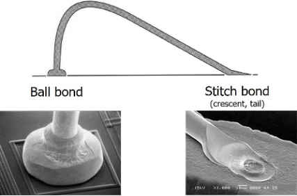
Wire bonding attaches a fine wire, usually 1 to 3 mils in diameter, from one connection pad to another, completing the electrical connection in an electronic device. The wire is attached to a compatible soft metal surface by pressing and vibrating the conductor against the metal surface for a determined period without using a filler metal alloy (solder) or extreme heat to cause fusion, see Figure 1. Today, it is estimated that more than 15 trillion wire bonds are made annually
[1]
Levine, L. (2016). Wire Bonding. Electronic Device Failure Analysis, Vol 18, No 1.
Gold, copper, and aluminum are the three most common metals used for wires and ribbons. Bonding wires and ribbons are commonly classified as either thin or thick. Thin wire or ribbon is < 75 microns, whereas thick wire or ribbon is ≥ 75 microns. Bonding wires come in a variety of diameters, and ribbons come in a variety of dimensions. Dopants are typically used in quantities ≤ 100 ppm to improve performance characteristics and reliability
[2]
Heraeus: Products and Solutions/Bonding Wires. Available from:
Gold wire was the original material used when wire bonding was developing. It has been the industry workhorse for over the last half-decade. It can be bonded in the shape of a ball or a wedge, with ball bonds accommodating very tight spacing. Gold wire works exceptionally well in low-loop and long-span applications. Gold wire offers broad operating parameters and can be used on virtually all types of bonding equipment.
Copper wire ball bonding has gained considerable attention due to its economic advantage, better electrical and thermal conductivity, and strong resistance to sweeping (leaning of the stress relief loop until it touches an adjacent bond wire). Copper enables smaller diameter wire with equivalent electrical and thermal performance. The migration to copper wire from gold has resulted in a more stringent and narrower wire bonding process window
[3]
Zhao, H., et. al. (2023). Research Progress on Bonding Wire for Microelectronic Packaging. Micromachines 14, 432.
Chan, M. J. (2020). Reliability study of copper wire bonding and through silicon via. Doctoral thesis, Nanyang Technological University, Singapore.
[3-5]
.
Aluminum wire has been used for bonding for decades. It is popular due to its good electrical performance and lower costs. Still, it is limited to wedge-to-wedge bonding due to its inability to form high-quality free-air balls (FAB). Wedge-to-wedge bonds enable fine pitch application due to the absence of a ball bond. However, there are trade-offs: alignment is required for the wire to be drawn straight from the first bond, causing limitations when spacing is tight and reducing throughput
[5]
Chan, M. J. (2020). Reliability study of copper wire bonding and through silicon via. Doctoral thesis, Nanyang Technological University, Singapore.
[5]
. Due to intermetallic compounds (IMC) that can form between the aluminum wire and gold-plated pad, keeping the plated gold to < 4 μ-inches is recommended.
3. Wire Bonding Methods
Wire bonding is a welding process where two metals are joined. Identical metals form an atomic weld (when sufficient thicknesses are present), similar metals form a diffusion bond, and dissimilar metals form intermetallic compound (IMC) bonds. The IMC is typically stronger and more brittle than the two base metals. Still, these bonds are subject to Kirkendall voiding (voids forming when one metal diffuses more rapidly into another). Atomic welds are preferred as they typically produce wire bonds with smaller variances. For all three bond types (atomic, diffusion, intermetallic), time and temperature allow the mixture to relax; stoichiometric equilibrium is reached as described by binary phase diagrams.
The magnitude of metallic adhesion depends on the metals' physical and chemical properties, the nature and extent of loading, and the characteristics of the contaminant layers present on all but atomically clean metal surfaces
[6]
Bowden, F. P., & Tabor, D. (1964). The friction and lubrication of solids. Oxford University Press, PA.
[6]
. Impurities at the bond site can lead to the Horsting Effect (contaminant accelerated voiding). It is, therefore, paramount that the bonding surface is pristine before bonding. This is typically accomplished using wet chemicals, e.g., isopropyl alcohol, or a dry chemical, e.g., plasma, cleaning immediately before bonding.
The three primary wire bonding techniques are thermo-compression, thermo-sonic, and ultrasonic. These three methods combine heat, pressure, and/or ultrasonic energy during bonding. Thermo-compression is not as common today due to the high heat and bond-force requirements.
Thermo-compression and thermo-sonic bonding methods produce a ball-stitch (first bond-second bond) type bond, where the stitch (tail, crescent, wedge, or second) bond lies on an arc about the ball bond. Thermo-compression bonding uses heat and force, whereas thermo-sonic bonding uses heat, pressure, and ultrasonic energy. Ultrasonic bonding (wedge bonding) produces a symmetric wedge-wedge (first bond-second bond) style bond. In ultrasonic bonding, the second bond must lie along the center line of the first. Ultrasonic bonding is performed at room temperature using pressure and energy
[5]
Chan, M. J. (2020). Reliability study of copper wire bonding and through silicon via. Doctoral thesis, Nanyang Technological University, Singapore.
[6]
Bowden, F. P., & Tabor, D. (1964). The friction and lubrication of solids. Oxford University Press, PA.
[7]
Charles, H. K. (2009). Advanced Wire Bonding Technology: Materials, Methods, and Testing. In: Lu, D., Wong, C. (eds) Materials for Advanced Packaging. Springer, Boston, MA.
[8]
Charles, H. K. (2010). The Microelectronic Wire Bond: Past, Present, and Future. IMAPS 2010 - 43rd International Symposium on Microelectronics. Raleigh, NC.
[5-8]
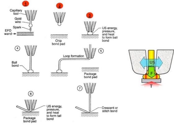
. A comparison of bonding techniques is shown in Table 1, and the thermos-sonic wire bonding cycle is depicted in Figure 2.
Five primary bond parameters affect bonding quality. These five parameters are touch-down velocity, bond force, ultrasonic energy, heat, and time. The general order of importance for bond reliability is discussed below
[1]
Levine, L. (2016). Wire Bonding. Electronic Device Failure Analysis, Vol 18, No 1.
[9]
Levine, L. (2020). Wire Bonding: The Ultrasonic Bonding Mechanism. 53rd International Symposium on Microelectronics, IMAPS Virtual Symposium, October 5-8, 2020.
[10]
Zhang, Y., et. al. (2025). Effect of Ultrasonic Power on the Morphology Evolution of Wedge Bonded Interface Between Al and Cu Wires, J. Phys.: Conf. Ser.,
Ultrasonic Power: mixes and diffuses the wire and the pad metals. The ultrasonic energy increases the dislocation density of the wire and bond site, lowering flow stress and the modulus of elasticity while increasing the diffusion rate. This makes the material deform easily at much lower stress than required and is commonly controlled in units of Watts, with a typical frequency of either 60 or 120 KHz. Touch-down Velocity: mates the surfaces together. Approximately 80% of the ball or wire deformation occurs on impact. Commonly controlled in units of microns-per-second. Bond Force: maintains intimate contact between the metals. Intimate contact is required for uniform and complete bonding and is commonly controlled in units of grams-force. Temperature: reduces the required activation energy needed for bonding. Targeting ~30% of the homologous temperature (having the same relation, relative position, or structure) allows the wire or ribbon slip planes to behave similarly. In other words, different metals (aluminum, gold, copper) move and behave similarly during bonding. Commonly controlled in units of Celsius. Time: allows complete, void-free bonds to form. Commonly controlled in units of milliseconds. Experiments (DoE) are often used to optimize these parameters
[1]
Levine, L. (2016). Wire Bonding. Electronic Device Failure Analysis, Vol 18, No 1.
[9]
Levine, L. (2020). Wire Bonding: The Ultrasonic Bonding Mechanism. 53rd International Symposium on Microelectronics, IMAPS Virtual Symposium, October 5-8, 2020.
[11]
Levine, L. (1995). The Ultrasonic Wedge Bonding Mechanism: Two Theories Converge. ISHM, p. 242-246.
[12]
Dongdong, F., et. al. (2023). Optimization of 25 μm Gold Wire Lead Bonding Process Parameters Based on Orthogonal Test. J. Phys.: Conf. Ser. 2524 012032,
Conventional immersion gold electrolytes function strictly by galvanic corrosion. A mixed reaction occurs in a reduction-assisted immersion gold (RAIG) electrolyte: an initial galvanic corrosion reaction followed by an autocatalytic reaction induced by a reducing agent
[13]
Carrillo, C., et. al. (2024). Next Generation Reduction Assisted Immersion Gold, Proceedings of the IPC Apex Expo, Anaheim, California, 6-11 April 2024.
[14]
Schafsteller, B., et. al. (2023). Enabling KCN-Free Stabilization for Mixed Reaction Gold Electrolytes, Proceedings of the IPC Apex Expo, San Deigo, California, 21-26 January 2023.
[13, 14]
. This allows the RAIG electrolyte to minimize the galvanic corrosion while allowing higher gold thickness capabilities on electroless nickel electroless palladium immersion gold (ENEPIG) compared to conventional immersion gold electrolytes. Thicker gold deposits open up the wire bonding process window and promote atomic welds between the gold wire or ribbon and the PCB pad. These benefits enable world-class quality "on target with minimal variation."
6. Case Study 1
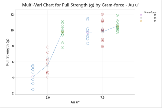
This case study evaluated two factors for their wire bonding effects. Two RAIG thicknesses, 2.0 μ-inches and 7.9 μ-inches (ENEPIG finish), and three bond gram-forces of 25, 50, and 75 grams were chosen. Before wire bonding, the samples were stress-conditioned for 16 hours at 175oC. Ten 1-mil gold wire bonds were made for each of the gold thicknesses. Pull testing was conducted per MIL-STD-883 Method 2011, Condition D. The pull results are shown in the multi-variate chart in Figure 3 and the analysis of variance (ANOVA) in Table 2.
Figure 3. Multi-variate chart of the pull results.
Table 2. ANOVA of the pull results.
Analysis of Variance for Pull Strength (g)
Source
DF
SS
MS
F
P
Au u"
1
188.38
188.38
147.82
< 0.01
Gram-force
2
113.4
56.699
44.49
< 0.01
Au u"*Gram-force
2
63.41
31.705
24.88
< 0.01
Error
54
68.82
1.274
Total
59
434.01
The multi-variate chart is a graphical representation of the relationships between the two factors and the response. This chart graphically represents the ANOVA table and is especially useful in detecting and understanding interactions. There is evidence of an interaction present; the effect of the bond gram-forces factor depends on the RAIG thickness, see Figure 3.
The ANOVA tests the hypothesis that the means of the RAIG thicknesses and bond gram-forces populations are equal. This is accomplished by comparing the response variable (mean pull strength) at the different factor levels (RAIG thicknesses, 2.0 and 7.9 μ-inches, and bond gram-forces, 25, 50, and 75 grams). The ANOVA corroborates the interaction between the Au μ-inches and the bond gram-force (Au u”*Gram-force); the interaction p-value is < 0.05 indicating statistical significance, see Table 2.
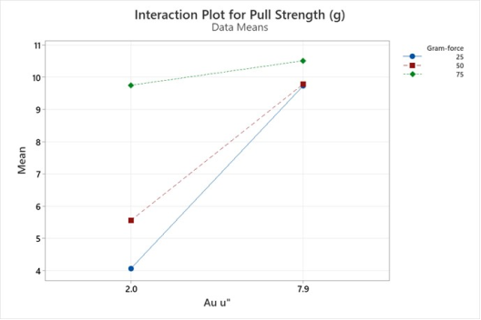
The interaction was further studied by creating an interaction plot. The effect of the bond gram-force factor depends on the RAIG thickness. At a RAIG thickness of 2.0 μ-inches, the bond gram-force is critical for wire pull strength. At a RAIG thickness of 7.9 μ-inches, the bond gram-force is not vital for wire pull strength, see Figure 4.
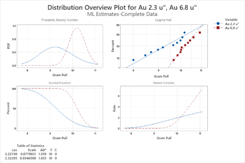
This case study evaluated a single factor for its wire bonding effects. Two RAIG thicknesses, 2.3 μ-inches and 6.8 μ-inches (ENEPIG finish) were chosen. Before wire bonding, the samples were stress-conditioned for 16 hours at 175oC. Ten 1-mil gold wire bonds were made for each of the gold thicknesses. Pull testing was conducted per MIL-STD-883 Method 2011, Condition D. Descriptive statistical data is recorded in Table 3, and fitted lognormal distributions are shown in Figure 5.
The wire pull results decisively pass the three-gram minimum required of MIL-STD-883 Method 2011, Condition D. The Coefficient of Variation (CV) is a measure of spread that describes the variation in the data relative to the mean. The CV is adjusted so that the values are on a unitless scale. Because of this adjustment, the CV can be used instead of the standard deviation to compare the variation in data with different means. While still very good, < 10% CV, the 2.3 μ-inch gold deposit has 2x the variation around the mean (7.8% vs 3.5%) and a lower overall mean (9.3g vs 10.2g) compared to the 6.8 μ-inch gold deposit. This is due to the thicker gold promoting atomic welds between the gold wire and the PCB pad, see Table 3.
Next, statistical testing for the equality of parameters was conducted. The location and scale are analogous to the mean and standard deviation for the lognormal distribution. Chi-square tests yielded p-values < 0.05 for both the location and scale, indicating a statistical difference. The thicker RAIG deposit statistically outperforms the thinner RAIG deposit. The test results for the equality of parameters are shown in Table 4.
Table 4. Tests for equality of parameters.
Test for Equal Location Parameters
Chi-Square
DF
P
12.2788
1
< 0.01
Test for Equal Scale Parameters
Chi-Square
DF
P
6.57626
1
0.01
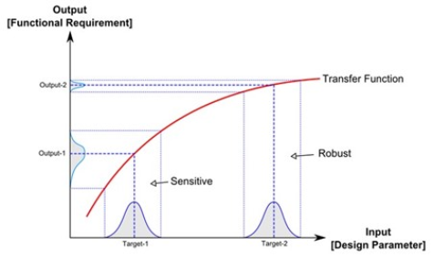
8. Robust Design
With a robust design, the aim is to make a process less sensitive to variation from the input factors
[15]
Eifler, T., Campean, F., Husung, S., Schleich, B. (2023). Perspectives on Robust Design – An Overview of Challenges and Research Areas Across Industry Fields, in Proceedings of the International Conference on Engineering Design (ICED23), Bordeaux, France, 24-28 July 2023.
Horber, D., et. al. (2024). Robust Conceptual Design for a Robust Early Embodiment Design. Norddesign Conference, Reykjavik, Iceland, 12-14 August 2024.
[15, 16]
. There is variation in the uncontrollable factors and transmitted variation in the controllable factors. In a robust design, controllable factors are set to levels that reduce variation in the response. This is often accomplished by using the signal-to-noise (S/N) ratio, which is a signal's power to the noise's power (error). The S/N is a single response that makes a trade-off between setting the mean to a desirable level and keeping the variance low. A conceptual model is shown in Figure 6. At a RAIG thickness of 2.0 μ-inches (Target 1), there is significant transmitted variation in the controllable factor bond gram-force (25-75 grams), whereas, at 7.9 μ-inches (Target 2), there is very little transmitted variation in the controllable factor bond gram-force (25-75 grams).
Wire bonding is a method used to attach a fine wire from one connection pad to another, completing an electrical circuit. Gold, copper, and aluminum are the three most common metals used for wires and ribbons. Three primary wire bonding techniques exist: thermo-compression, thermo-sonic, and ultrasonic. There are five primary bonding parameters: touch-down velocity, bond force, ultrasonic energy, heat, and time. A mixed reaction RAIG electrolyte minimizes galvanic corrosion while allowing higher gold thickness capabilities on ENEPIG, enabling robust designs and achieving world-class quality "on target with minimal variation."
Chan, M. J. (2020). Reliability study of copper wire bonding and through silicon via. Doctoral thesis, Nanyang Technological University, Singapore.
[6]
Bowden, F. P., & Tabor, D. (1964). The friction and lubrication of solids. Oxford University Press, PA.
[7]
Charles, H. K. (2009). Advanced Wire Bonding Technology: Materials, Methods, and Testing. In: Lu, D., Wong, C. (eds) Materials for Advanced Packaging. Springer, Boston, MA.
[8]
Charles, H. K. (2010). The Microelectronic Wire Bond: Past, Present, and Future. IMAPS 2010 - 43rd International Symposium on Microelectronics. Raleigh, NC.
[9]
Levine, L. (2020). Wire Bonding: The Ultrasonic Bonding Mechanism. 53rd International Symposium on Microelectronics, IMAPS Virtual Symposium, October 5-8, 2020.
[10]
Zhang, Y., et. al. (2025). Effect of Ultrasonic Power on the Morphology Evolution of Wedge Bonded Interface Between Al and Cu Wires, J. Phys.: Conf. Ser.,
Levine, L. (1995). The Ultrasonic Wedge Bonding Mechanism: Two Theories Converge. ISHM, p. 242-246.
[12]
Dongdong, F., et. al. (2023). Optimization of 25 μm Gold Wire Lead Bonding Process Parameters Based on Orthogonal Test. J. Phys.: Conf. Ser. 2524 012032,
Carrillo, C., et. al. (2024). Next Generation Reduction Assisted Immersion Gold, Proceedings of the IPC Apex Expo, Anaheim, California, 6-11 April 2024.
[14]
Schafsteller, B., et. al. (2023). Enabling KCN-Free Stabilization for Mixed Reaction Gold Electrolytes, Proceedings of the IPC Apex Expo, San Deigo, California, 21-26 January 2023.
[15]
Eifler, T., Campean, F., Husung, S., Schleich, B. (2023). Perspectives on Robust Design – An Overview of Challenges and Research Areas Across Industry Fields, in Proceedings of the International Conference on Engineering Design (ICED23), Bordeaux, France, 24-28 July 2023.
Horber, D., et. al. (2024). Robust Conceptual Design for a Robust Early Embodiment Design. Norddesign Conference, Reykjavik, Iceland, 12-14 August 2024.
Valentine, P. (2025). Evaluating Gold Wire Bonding Pull Strengths on Different Thicknesses of Reduction-Assisted Immersion Gold. Science Journal of Circuits, Systems and Signal Processing, 12(1), 1-7. https://doi.org/10.11648/j.cssp.20251201.11
Valentine, P. Evaluating Gold Wire Bonding Pull Strengths on Different Thicknesses of Reduction-Assisted Immersion Gold. Sci. J. Circuits Syst. Signal Process.2025, 12(1), 1-7. doi: 10.11648/j.cssp.20251201.11
Valentine P. Evaluating Gold Wire Bonding Pull Strengths on Different Thicknesses of Reduction-Assisted Immersion Gold. Sci J Circuits Syst Signal Process. 2025;12(1):1-7. doi: 10.11648/j.cssp.20251201.11
@article{10.11648/j.cssp.20251201.11,
  author = {Patrick Valentine},
  title = {Evaluating Gold Wire Bonding Pull Strengths on Different Thicknesses of Reduction-Assisted Immersion Gold
},
  journal = {Science Journal of Circuits, Systems and Signal Processing},
  volume = {12},
  number = {1},
  pages = {1-7},
  doi = {10.11648/j.cssp.20251201.11},
  url = {https://doi.org/10.11648/j.cssp.20251201.11},
  eprint = {https://article.sciencepublishinggroup.com/pdf/10.11648.j.cssp.20251201.11},
  abstract = {Wire bonding attaches a fine wire from one connection pad to another, completing an electrical connection. Reduction-assisted immersion gold (RAIG) has recently gained popularity due to its ability to eliminate corrosion and plate thicker gold deposits. Implementing a RAIG process improves quality and reduces wire bonding product reliability risk. The purpose of this research was two-fold: 1) evaluate the effects of crossing two RAIG thicknesses against three wire bonding gram-forces on wire bond pull strength, and 2) evaluate two independent RAIG thickness effects on wire bond pull strength, all on an electroless nickel electroless palladium immersion gold (ENEPIG) final finished printed circuit board. A quantitative, experimental research methodology was used to manipulate independent variables to observe the effect on the dependent variable, establishing cause-and-effect relationships for wire bonding. This method was selected because of its ability to identify and quantify statistically significant factors for gold plating and wire bonding. Data was generated and collected in a controlled laboratory setting. Multi-variate charts, analysis of variance (ANOVA), lognormal distributions, and descriptive statistics were used for data analysis. As the RAIG deposit thickness increases, the bond gram-force is not vital for wire pull strength. Thicker RAIG deposits statistically outperform thinner RAIG deposits for wire pull strength. A mixed reaction RAIG electrolyte enables robust designs and achieves world-class quality "on target with minimal variation."
},
 year = {2025}
}
TY  - JOUR
T1  - Evaluating Gold Wire Bonding Pull Strengths on Different Thicknesses of Reduction-Assisted Immersion Gold

AU  - Patrick Valentine
Y1  - 2025/06/19
PY  - 2025
N1  - https://doi.org/10.11648/j.cssp.20251201.11
DO  - 10.11648/j.cssp.20251201.11
T2  - Science Journal of Circuits, Systems and Signal Processing
JF  - Science Journal of Circuits, Systems and Signal Processing
JO  - Science Journal of Circuits, Systems and Signal Processing
SP  - 1
EP  - 7
PB  - Science Publishing Group
SN  - 2326-9073
UR  - https://doi.org/10.11648/j.cssp.20251201.11
AB  - Wire bonding attaches a fine wire from one connection pad to another, completing an electrical connection. Reduction-assisted immersion gold (RAIG) has recently gained popularity due to its ability to eliminate corrosion and plate thicker gold deposits. Implementing a RAIG process improves quality and reduces wire bonding product reliability risk. The purpose of this research was two-fold: 1) evaluate the effects of crossing two RAIG thicknesses against three wire bonding gram-forces on wire bond pull strength, and 2) evaluate two independent RAIG thickness effects on wire bond pull strength, all on an electroless nickel electroless palladium immersion gold (ENEPIG) final finished printed circuit board. A quantitative, experimental research methodology was used to manipulate independent variables to observe the effect on the dependent variable, establishing cause-and-effect relationships for wire bonding. This method was selected because of its ability to identify and quantify statistically significant factors for gold plating and wire bonding. Data was generated and collected in a controlled laboratory setting. Multi-variate charts, analysis of variance (ANOVA), lognormal distributions, and descriptive statistics were used for data analysis. As the RAIG deposit thickness increases, the bond gram-force is not vital for wire pull strength. Thicker RAIG deposits statistically outperform thinner RAIG deposits for wire pull strength. A mixed reaction RAIG electrolyte enables robust designs and achieves world-class quality "on target with minimal variation."

VL  - 12
IS  - 1
ER  -
Technical Department, Uyemura USA, Southington, The United States
Biography:
Patrick Valentine Technical and Lean Six Sigma Manager for Uyemura USA (uyemura.com). He holds a Doctorate Degree in Quality Systems Management from Cambridge College, a Six Sig-ma Master Black Belt certification from Arizona State University, and ASQ certifications as a Six Sigma Black Belt and Reliability Engineer.
Valentine, P. (2025). Evaluating Gold Wire Bonding Pull Strengths on Different Thicknesses of Reduction-Assisted Immersion Gold. Science Journal of Circuits, Systems and Signal Processing, 12(1), 1-7. https://doi.org/10.11648/j.cssp.20251201.11
Valentine, P. Evaluating Gold Wire Bonding Pull Strengths on Different Thicknesses of Reduction-Assisted Immersion Gold. Sci. J. Circuits Syst. Signal Process.2025, 12(1), 1-7. doi: 10.11648/j.cssp.20251201.11
Valentine P. Evaluating Gold Wire Bonding Pull Strengths on Different Thicknesses of Reduction-Assisted Immersion Gold. Sci J Circuits Syst Signal Process. 2025;12(1):1-7. doi: 10.11648/j.cssp.20251201.11
@article{10.11648/j.cssp.20251201.11,
  author = {Patrick Valentine},
  title = {Evaluating Gold Wire Bonding Pull Strengths on Different Thicknesses of Reduction-Assisted Immersion Gold
},
  journal = {Science Journal of Circuits, Systems and Signal Processing},
  volume = {12},
  number = {1},
  pages = {1-7},
  doi = {10.11648/j.cssp.20251201.11},
  url = {https://doi.org/10.11648/j.cssp.20251201.11},
  eprint = {https://article.sciencepublishinggroup.com/pdf/10.11648.j.cssp.20251201.11},
  abstract = {Wire bonding attaches a fine wire from one connection pad to another, completing an electrical connection. Reduction-assisted immersion gold (RAIG) has recently gained popularity due to its ability to eliminate corrosion and plate thicker gold deposits. Implementing a RAIG process improves quality and reduces wire bonding product reliability risk. The purpose of this research was two-fold: 1) evaluate the effects of crossing two RAIG thicknesses against three wire bonding gram-forces on wire bond pull strength, and 2) evaluate two independent RAIG thickness effects on wire bond pull strength, all on an electroless nickel electroless palladium immersion gold (ENEPIG) final finished printed circuit board. A quantitative, experimental research methodology was used to manipulate independent variables to observe the effect on the dependent variable, establishing cause-and-effect relationships for wire bonding. This method was selected because of its ability to identify and quantify statistically significant factors for gold plating and wire bonding. Data was generated and collected in a controlled laboratory setting. Multi-variate charts, analysis of variance (ANOVA), lognormal distributions, and descriptive statistics were used for data analysis. As the RAIG deposit thickness increases, the bond gram-force is not vital for wire pull strength. Thicker RAIG deposits statistically outperform thinner RAIG deposits for wire pull strength. A mixed reaction RAIG electrolyte enables robust designs and achieves world-class quality "on target with minimal variation."
},
 year = {2025}
}
TY  - JOUR
T1  - Evaluating Gold Wire Bonding Pull Strengths on Different Thicknesses of Reduction-Assisted Immersion Gold

AU  - Patrick Valentine
Y1  - 2025/06/19
PY  - 2025
N1  - https://doi.org/10.11648/j.cssp.20251201.11
DO  - 10.11648/j.cssp.20251201.11
T2  - Science Journal of Circuits, Systems and Signal Processing
JF  - Science Journal of Circuits, Systems and Signal Processing
JO  - Science Journal of Circuits, Systems and Signal Processing
SP  - 1
EP  - 7
PB  - Science Publishing Group
SN  - 2326-9073
UR  - https://doi.org/10.11648/j.cssp.20251201.11
AB  - Wire bonding attaches a fine wire from one connection pad to another, completing an electrical connection. Reduction-assisted immersion gold (RAIG) has recently gained popularity due to its ability to eliminate corrosion and plate thicker gold deposits. Implementing a RAIG process improves quality and reduces wire bonding product reliability risk. The purpose of this research was two-fold: 1) evaluate the effects of crossing two RAIG thicknesses against three wire bonding gram-forces on wire bond pull strength, and 2) evaluate two independent RAIG thickness effects on wire bond pull strength, all on an electroless nickel electroless palladium immersion gold (ENEPIG) final finished printed circuit board. A quantitative, experimental research methodology was used to manipulate independent variables to observe the effect on the dependent variable, establishing cause-and-effect relationships for wire bonding. This method was selected because of its ability to identify and quantify statistically significant factors for gold plating and wire bonding. Data was generated and collected in a controlled laboratory setting. Multi-variate charts, analysis of variance (ANOVA), lognormal distributions, and descriptive statistics were used for data analysis. As the RAIG deposit thickness increases, the bond gram-force is not vital for wire pull strength. Thicker RAIG deposits statistically outperform thinner RAIG deposits for wire pull strength. A mixed reaction RAIG electrolyte enables robust designs and achieves world-class quality "on target with minimal variation."

VL  - 12
IS  - 1
ER  -